
Engine cylinder pressure testing tool

A technology for engine cylinder and pressure testing, applied in the direction of internal combustion engine testing, etc., can solve the problems of reduced test accuracy, small test results, and easily damaged rubber plugs, and achieves the effects of convenient connection, improved accuracy, and less damage.

Inactive Publication Date: 2017-03-15
CHONGQING SOKON IND GRP CO LTD
View PDF8 Cites 0 Cited by
  • Summary
  • Abstract
  • Description
  • Claims
  • Application Information

AI Technical Summary

Problems solved by technology

Cylinder pressure detection is one of the more important indicators. In the existing technology, whether it is a gasoline engine or a diesel engine, the technology for cylinder pressure detection is very mature. The cylinder pressure gauge is mainly used for measurement. The specific method is that the cylinder pressure A test tube is installed on the pressure gauge, and a tapered rubber plug is installed on the head of the test tube. After the spark plug is removed from the engine, the tapered rubber plug is pressed against the position of the spark plug for testing. The pressure of the test tube is different, and the same engine is tested by different workers. The test results are different and the error is relatively large. Part of the cylinder volume, the cylinder pressure tested by the cylinder pressure gauge is the volume pressure of the test tube volume and the volume of the piston cylinder, which will invisibly cause the compressed volume of the piston cylinder to become larger, the test result is too small, and the test accuracy is greatly reduced

Method used


Image

  • Engine cylinder pressure testing tool
  • Engine cylinder pressure testing tool

Examples


Embodiment Construction

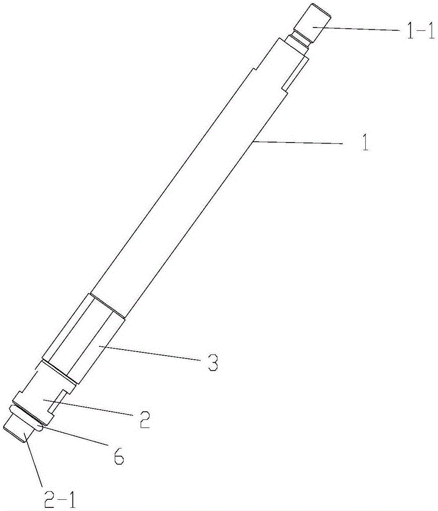
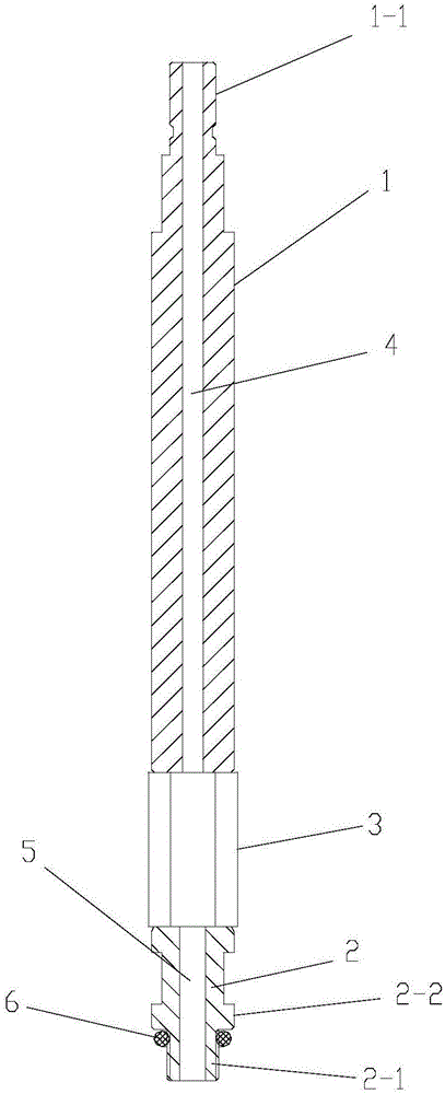
[0017] figure 1 It is an overall schematic diagram of the structure of the present invention, figure 2 It is a cross-sectional view of the structure of the present invention, as shown in the figure: the engine cylinder pressure test tooling of this embodiment includes a test tube 1 at the upper end for installing a cylinder pressure gauge, a tubular connector 2 at the lower end for connecting with the cylinder bore of the engine, and connection settings A one-way valve 3 between the upper end of the tubular connector 2 and the lower end of the test tube 1; Connector 2, test hole 4 is formed in the test tube 1, the tubular connector 2 is hollow to form a flow hole 5, and the one-way valve 3 controls the one-way flow of compressed gas from the tubular connector 2 to the test tube 1, and the one-way valve 3 can be a spring The plunger check valve 3 may be a diaphragm check valve 3; in addition, the test tube 1 may be a straight rod structure or a hose structure, and the tubular...


PUM


Abstract

The present invention discloses an engine cylinder pressure testing tool, which comprises a test tube, a tubular connector and a non-return valve. The upper end of the test tube is used for the installation of a cylinder pressure gauge. The lower end of the tubular connector is used for the connection of an engine cylinder hole. The non-return valve is connected between the upper end of the tubular connector and the lower end of the test tube. The test tube is provided with the non-return valve, and the non-return valve is positioned closer to the cylinder hole and is connected with the tubular connector. The length of the tubular connector is far smaller than the length of the test tube. The non-return valve controls the compressed gas to flow unidirectionally from the tubular connector to the test tube. In this way, the volume of a combustion chamber, tested by the cylinder pressure gauge, is closer to the normal engine combustion volume instead of the volume sum of the engine cylinder and the test tube. Therefore, the accuracy of the test result is greatly improved. Moreover, the testing tool is connected with the cylinder hole through the tubular connector, so that the connection is convenient. The testing tool is not easily damaged, and is free from being manually pressed by an external worker. Therefore, test results are ensured to be consistent when the testing tool is operated by different workers.

Description

technical field [0001] The invention relates to the field of engine performance testing, in particular to an engine cylinder pressure testing tool. Background technique [0002] In the design and development of engine products, it is necessary to conduct bench tests of the engine to detect the operating conditions of the engine and obtain performance parameters during its operation, such as the pressure in the engine cylinder and the air leakage of the cylinder, so as to be used in the design During the process, according to the bench test results, adjustments, corrections and supplements are made to the shape, result, size and relative connection position of the product, and even the materials used, so as to obtain the ideal product design effect. Cylinder pressure detection is one of the more important indicators. In the existing technology, whether it is a gasoline engine or a diesel engine, the technology for cylinder pressure detection is very mature. The cylinder press...

Claims


Application Information

Patent Timeline
IPC IPC(8): G01M15/08
CPCG01M15/08
Inventor 陈柯良
Owner CHONGQING SOKON IND GRP CO LTD
Learn More