

Method for measuring fluorescence lifetime of probe molecule based on pressure-sensitive coating
A fluorescence lifetime and paint technology, applied in fluorescence/phosphorescence, material excitation analysis, etc., can solve problems such as changes in paint light intensity, difficult registration algorithm correction, etc., to achieve the effects of reducing errors, suppressing motion blur, and improving data accuracy
Active Publication Date: 2017-03-15
AVIC SHENYANG AERODYNAMICS RES INST
View PDF7 Cites 29 Cited by
- Summary
- Abstract
- Description
- Claims
- Application Information
AI Technical Summary
Problems solved by technology
However, the local light intensity change of the paint caused by the deformation is difficult to be corrected by the registration algorithm
Method used
View moreImage
Smart ImageViewing Examples

Examples
Embodiment 1
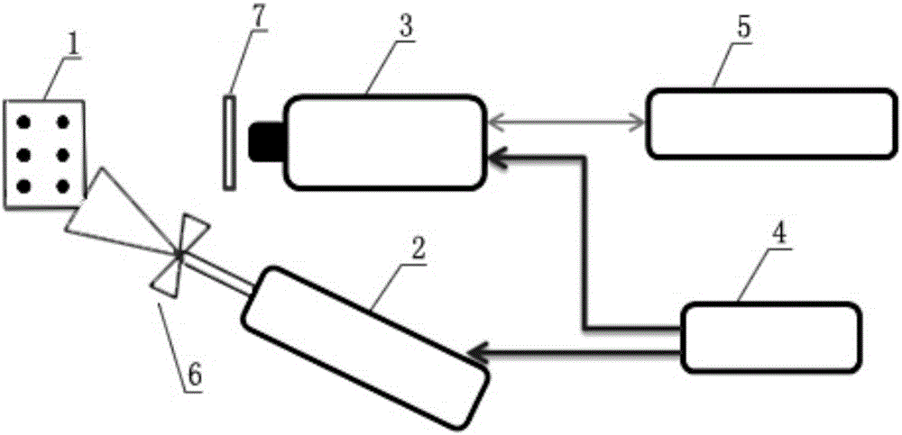
[0026] Such as Figure 1-3 As shown, a measurement method based on the fluorescence lifetime of pressure-sensitive paint probe molecules, the adopted system includes a pulse excitation light source 2, an acquisition camera 3, a synchronization controller 4, a computer 5, a concave lens 6 and an optical filter 7,
Login to View More PUM
 Abstract
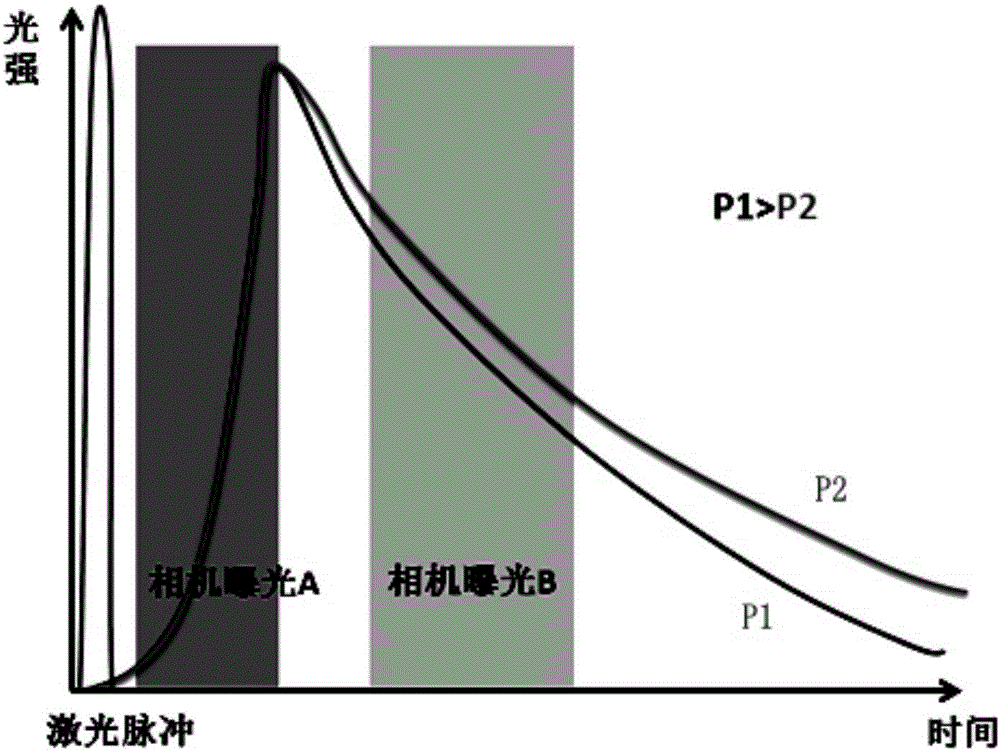
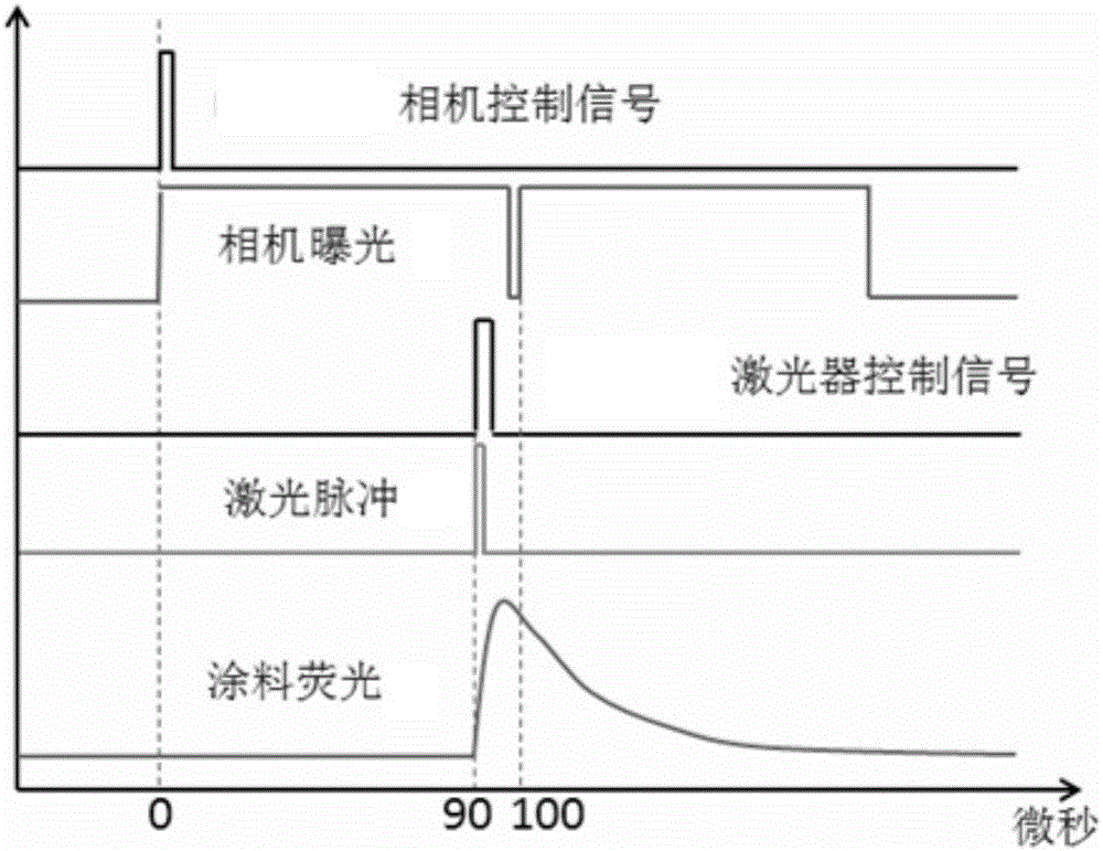
The invention relates to a method for measuring fluorescence lifetime of a probe molecule based on a pressure-sensitive coating. An adopted system comprises a pulse excitation light source, a collection camera, a synchronous controller, a computer, a concave lens and a filter. The method comprises the following steps of enabling a pulse light source to excite the coating, quickly exposing twice by the collection camera, and collecting fluorescence light intensity information. The method has the advantages that data is processed by a secondary comparison method, so that the error caused by matching of an experiment image and a reference image of a target with deformation is reduced; a PIV (particle image velocimetry) green optical maser is used for exciting, so that the exposure time is greatly shortened by a high-energy pulse light source, and the movement fuzzy defect is weakened; the system can be applied to the PSP / TSP (personal software process / team software process) measuring experiment of a rotary part.
Description
technical field [0001] The invention relates to a measurement method based on pressure-sensitive paint probe molecular fluorescence lifetime. Background technique [0002] Pressure-sensitive paint pressure measurement technology is a non-contact optical pressure measurement technology with broad development prospects. It has the characteristics of low interference to the flow field and high spatial resolution. It is widely used in various wind tunnel pressure measurement experiments abroad. among. And its inherent advantage of not needing additional modifications to the model makes it one of the most potential pressure measurement technologies in the experimental environment of rotating parts represented by compressors. [0003] Most of the traditional PSP measurement techniques are based on fluorescence light intensity, that is, to simply detect the light intensity value of the paint and construct the relationship between the value and the local pressure. This method has c...
Claims
Login to View More Application Information
Patent Timeline
 IPC IPC(8): G01N21/64
CPCG01N21/64
Inventor衷洪杰尚金奎赵荣奂王鹏赵民王天旭
OwnerAVIC SHENYANG AERODYNAMICS RES INST