Unmanned aerial vehicle camera lens

A camera lens and UAV technology, applied in the field of lens, can solve the problems that affect the imaging quality of the camera lens of the drone, the camera lens cannot adapt to the temperature environment, and the temperature has a great influence on the camera lens, so as to ensure the quality of resolution, high Quality Resolution, Lightweight Effects

Active Publication Date: 2017-03-15
JIANGXI LIANYI OPTICS CO LTD
View PDF6 Cites 9 Cited by
  • Summary
  • Abstract
  • Description
  • Claims
  • Application Information

AI Technical Summary

Problems solved by technology

[0003] Among the existing technologies, the camera lenses currently used on UAVs generally have defects such as low resolution quality, difficult processing, poor temperature control, and purple fringing, which seriously affect the imaging quality of UAV camera lenses. Some important factors restricting the development of drones, especially due to the poor temperature control of the camera lens, will lead to a greater impact of temperature on the camera lens, making the camera lens unable to adapt to different temperature occasions

Method used


Image

  • Unmanned aerial vehicle camera lens
  • Unmanned aerial vehicle camera lens
  • Unmanned aerial vehicle camera lens

Examples


Embodiment 1

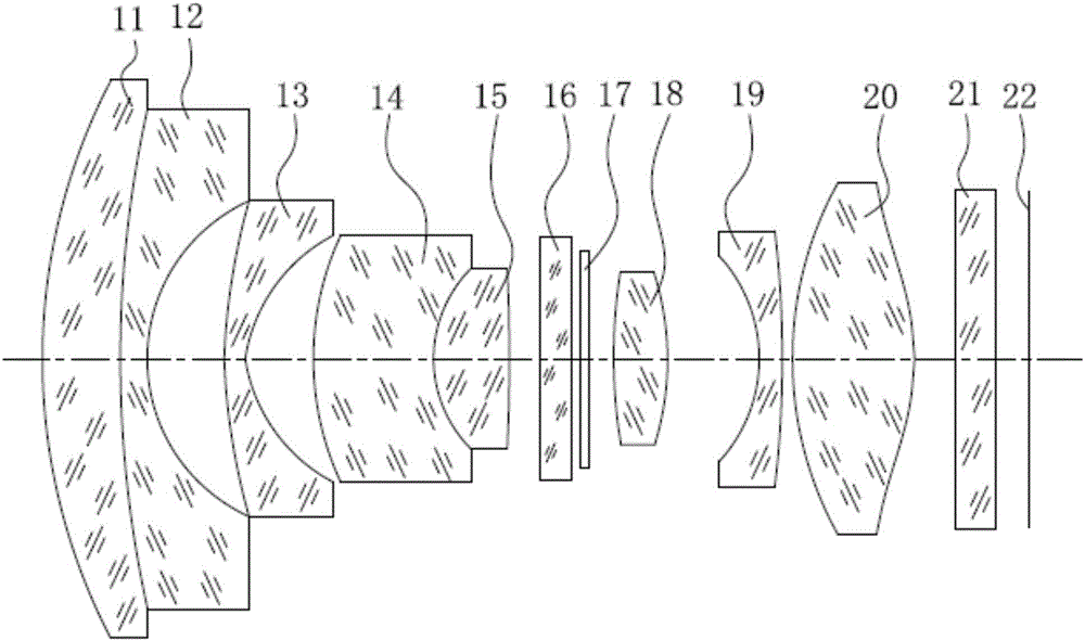
[0063] see Figure 1a , which is a schematic diagram of the cross-sectional structure of the UAV camera lens in the first embodiment of the present invention, which includes a first lens 11 with positive refractive power and a second lens 12 with negative refractive power in sequence from the object side to the imaging surface , a third lens 13 with negative power, a fourth lens 14 with negative power, a fifth lens 15 with positive power, an optical filter 16, an aperture 17, a sixth lens with positive power 18. A seventh lens 19 with negative refractive power, an eighth lens 20 with positive refractive power, a cover glass 21 and an imaging surface 22 . Wherein, the optical centers of each lens are located on the same straight line, and all the lenses of the drone camera lens are coated with a high transmittance multilayer film.

[0064] Specifically, the first lens 11 is a meniscus-shaped glass spherical lens with a concave surface facing the imaging surface, and the second ...

Embodiment 2

[0108] see Figure 2a , which is a schematic cross-sectional structure diagram of the UAV camera lens in the second embodiment of the present invention, the UAV camera lens in this embodiment is roughly the same as the UAV camera lens in the first embodiment, the difference The reason is that there are differences between the relevant parameters of the lenses of the camera lens of the drone in this embodiment and the parameters of the lenses of the camera lens of the drone in the first embodiment.

[0109] Please refer to Table 3, which shows the relevant parameters of each lens of the drone camera lens in this embodiment.

[0110] table 3:

[0111]

[0112]

[0113] Please refer to Table 4, which shows the relevant parameters of the aspheric surface of the camera lens of the drone in the present embodiment.

[0114] Table 4:

[0115]

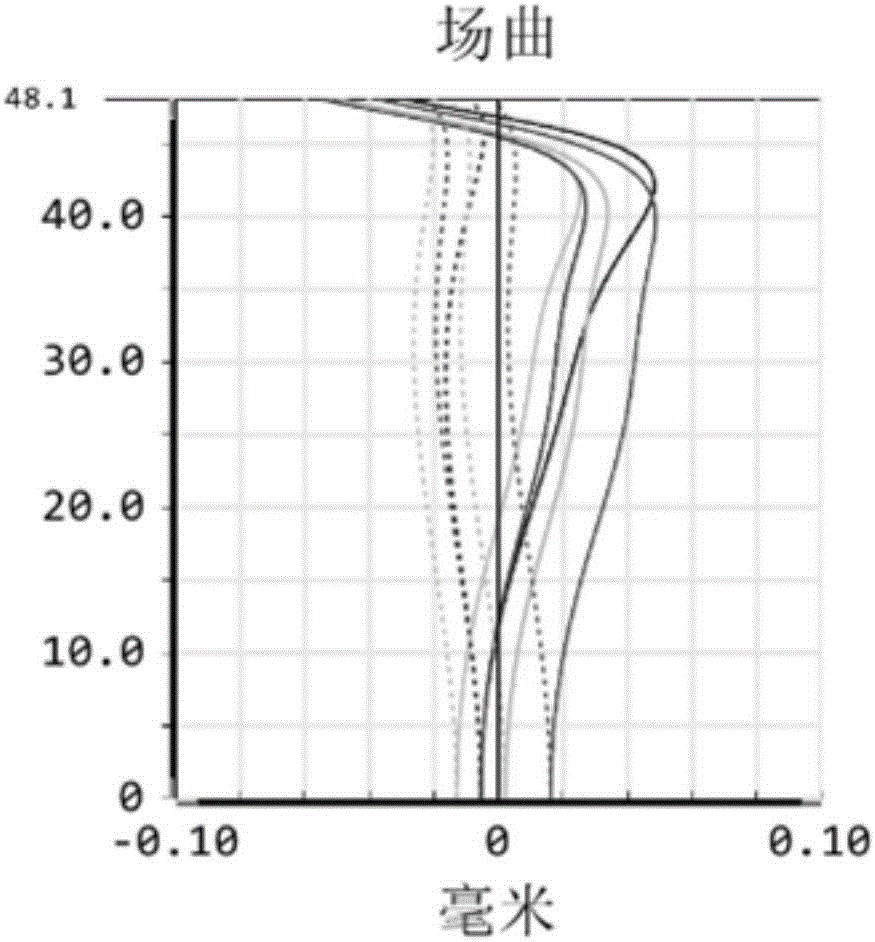
[0116] see Figure 2b , shown as the field curvature curve of the drone camera lens in this embodiment, please refer to Figure ...

Embodiment 3

[0118] see Figure 3a , which is a schematic cross-sectional structure diagram of the UAV camera lens in the third embodiment of the present invention, the UAV camera lens in this embodiment is roughly the same as the UAV camera lens in the first embodiment, the difference That is, the UAV camera lens in this embodiment is based on the first embodiment, the first lens 11 and the second lens 12 are separated independently, and the two are used separately instead of being combined into a cemented lens, At the same time, there are differences in the relevant parameters of the lenses of the camera lens of the drone in this implementation and the parameters of the lenses of the camera lens of the drone in the first embodiment.

[0119] Please refer to Table 5, which shows the relevant parameters of each lens of the drone camera lens in this embodiment.

[0120] table 5:

[0121]

[0122]

[0123] Please refer to Table 6, which shows the relevant parameters of the aspheric s...


PUM


Abstract

The invention provides an unmanned aerial vehicle (UAV) camera lens. The camera lens sequentially comprises, from the object side to the imaging plane, a first lens, a second lens, a third lens, a fourth lens, a fifth lens, a diaphragm, a sixth lens, a seventh lens, and an eighth lens. The first lens, the second lens and the fourth lens are glass spherical lenses which are meniscus-shaped and concaved toward the imaging plane. The third lens is a glass aspheric lens which is meniscus-shaped and concaved toward the imaging plane. The fifth lens and the sixth lens are biconvex glass spherical lenses. The fifth lens and the fourth lens form an agglutinated lens. The seventh lens is a glass spherical lens which is meniscus-shaped and concaved toward the object side. The eighth lens is a biconvex glass aspheric lens. All the lenses of the UAV camera lens are made of glass. The UAV camera lens can adapt to different temperature occasions. The UAV camera lens has the advantages of good temperature control effect, clear imaging, high sharpness, and high resolution quality. The number of pixels is at least above 12 millions.

Description

technical field [0001] The invention relates to the technical field of lenses, in particular to an unmanned aerial vehicle camera lens. Background technique [0002] With the continuous development of science and technology, in recent years, the UAV industry has developed rapidly. UAVs are usually used for aerial photography, detectives, surveillance, communications, anti-submarine, electronic interference, etc. important tool. [0003] Among the existing technologies, the camera lenses currently used on UAVs generally have defects such as low resolution quality, difficult processing, poor temperature control, and purple fringing, which seriously affect the imaging quality of UAV camera lenses. Some important factors restricting the development of drones, especially due to the poor temperature control of the camera lens, will cause a greater impact of temperature on the camera lens, making the camera lens unable to adapt to different temperature occasions. Contents of the...

Claims


Application Information

Patent Timeline
Patent Type & Authority Applications(China)
IPC IPC(8): G02B13/00G02B13/06G02B13/18G02B1/00
CPCG02B13/0045G02B13/006G02B13/06G02B13/18G02B1/00
Inventor 李伟娜高博
Owner JIANGXI LIANYI OPTICS CO LTD
Why Eureka
Try Eureka