A kind of industrial robot tcp calibration method

An industrial robot and calibration method technology, applied in the field of industrial robot tool coordinate system origin calibration, can solve problems such as unreliable calibration results, and achieve the effects of improving calibration reliability, calculation accuracy, and eliminating errors

Active Publication Date: 2018-04-27
FOSHAN HUASHU ROBOTICS CO LTD
View PDF13 Cites 2 Cited by
  • Summary
  • Abstract
  • Description
  • Claims
  • Application Information

AI Technical Summary

Problems solved by technology

[0003] The technical problem to be solved by the present invention is: solve the problem of unreliable calibration results

Method used


Image

  • A kind of industrial robot tcp calibration method
  • A kind of industrial robot tcp calibration method
  • A kind of industrial robot tcp calibration method

Examples


Embodiment 1

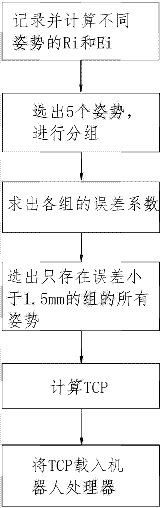
[0033] In order to verify the specific implementation of the present invention, check is carried out on the robot simulation software. The theoretical TCP of the robot tool used for simulation is (2, 0, 402), such as figure 1 The flow chart of the steps shown, the execution steps are roughly as follows:

[0034] 1) Teaching the robot to make the tool to be calibrated touch the tip of a fixed sharp object in the flexible working space of the robot in different postures, record the joint angle coordinates or Cartesian coordinates of each posture, and calculate the flange plate coordinates of the connecting rod end of each posture The attitude matrix R of the system i (i=1, 2..., n) and displacement vector E i (i=1, 2, ..., n);

[0035] Record the joint angle coordinates of the six-axis robot for 5 poses, and get Table 1;

[0036]

[0037] Table 1

[0038] The attitude matrix R of the flange coordinate system at the end of the connecting rod of each attitude can be obtain...

Embodiment 2

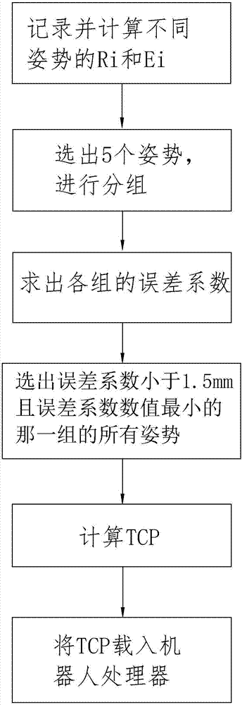
[0069] In order to verify the specific implementation of the present invention, check is carried out on the robot simulation software. The theoretical TCP of the tool for simulating the robot is (2, 0, 402), such as figure 2 The flow chart of the steps shown, the execution steps are roughly as follows:

[0070] 1) The teaching robot makes the origin of the tool coordinate system TCP to be calibrated touch the tip of a fixed pointed object in the flexible workspace of the robot in different postures, records the joint angle coordinates or Cartesian coordinates of each posture, and calculates the end of the connecting rod of each posture The attitude matrix R of the flange coordinate system i (i=1, 2..., n) and displacement vector E i (i=1, 2, ..., n);

[0071] Record the joint angle coordinates of the six-axis robot for 5 postures, and get Table 3;

[0072]

[0073] table 3

[0074] The attitude matrix and displacement vector of the flange coordinate system at the end ...


PUM


Abstract

The invention discloses an industrial robot TCP calibration method, which comprises the steps of teaching, recording postures and calculating an attitude matrix and a displacement vector of a connecting rod tail end flange plate coordinate system of each posture; then firstly solving a least square solution Q of an over-determined equation set for TCP calibration, eliminating an error once, then solving a least square solution of TCP by using the least square solution Q, and further eliminating the error, thereby enabling the overall calculation to be more accurate, and improving the calibration reliability.

Description

technical field [0001] The invention relates to the technical field of industrial robots, in particular to a method for calibrating the origin of a tool coordinate system of an industrial robot. Background technique [0002] Industrial robots need to use tools installed on the flange at the end of the manipulator to complete various industrial tasks. Programmers want the robot tools to run according to a certain trajectory, so the installed tools need to be calibrated. In the multi-point calibration method without any auxiliary equipment, the "four-point calibration" method is mostly used. However, the accuracy of the "four-point calibration" method is not high, and the error is large, which makes the calibration results unreliable. Contents of the invention [0003] The technical problem to be solved by the invention is to solve the problem of unreliable calibration results. [0004] The solution that the present invention solves its technical problem is: a kind of indu...

Claims


Application Information

Patent Timeline
Patent Type & Authority Patents(China)
IPC IPC(8): G05B19/408
CPCG05B19/4083G05B2219/35356
Inventor 周星黄石峰王群杨海滨李帆
Owner FOSHAN HUASHU ROBOTICS CO LTD
Why Eureka
Try Eureka