Automatic calibration method and apparatus for receiver's amplitude-frequency response

An amplitude-frequency response and receiver technology, which is applied in the field of receiver amplitude-frequency response automatic calibration, can solve the problems of unstable signal source, missing intermediate errors, and long calibration process, so as to enrich the power error database and ensure measurement accuracy , Calibration point selection reasonable effect

Active Publication Date: 2017-03-15
SHENZHEN CITY SIGLENT TECH
View PDF5 Cites 9 Cited by
  • Summary
  • Abstract
  • Description
  • Claims
  • Application Information

AI Technical Summary

Problems solved by technology

However, the traditional method is often affected by unstable signal sources or other environmental factors, making it difficult to determine the step size and difficult to select calibration points, resulting in calibration errors
For a receiver with a large test frequency range, a large step may cause frequency points with large intermediate errors to be missed, and too small a step will make the calibration process take too long. In addition, due to the discrete hardware characteristics of each receiver The selected calibration points cannot reflect the amplitude-frequency response characteristics of each receiver very well

Method used


Image

  • Automatic calibration method and apparatus for receiver's amplitude-frequency response
  • Automatic calibration method and apparatus for receiver's amplitude-frequency response
  • Automatic calibration method and apparatus for receiver's amplitude-frequency response

Examples


Embodiment 1

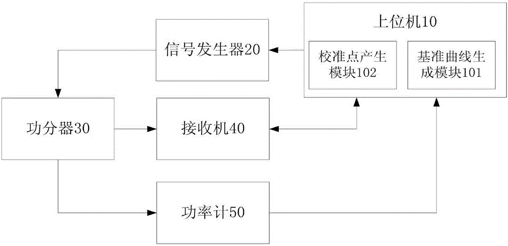
[0038] Please refer to figure 1 , the present application provides an automatic calibration device for amplitude-frequency response of a receiver, including: a signal generator 20 , a power divider 30 , a power meter 50 , a receiver 40 and a host computer 10 .

[0039] Signal generator 20 is connected with power divider 30, host computer 10, and signal generator 20 is as signal source, and the frequency value and output power that it sends test signal is set by host computer 10; In the present embodiment, signal generator 20 Send a test signal with a step change in frequency etc. to the power divider 30 .

[0040]The power splitter 30 is connected with the power meter 50 and the receiver 40 , and divides the test signal into two paths to transmit to the power meter 50 and the receiver 40 respectively.

[0041] The receiver 40 measures and obtains a power measurement value, and there is a certain error between the power measurement value and the actual power value.

[0042] T...

Embodiment 2

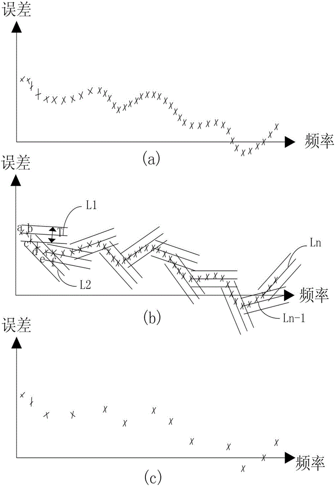
[0063] Please refer to image 3 with Figure 4 , the application provides a data selection method, including steps:

[0064] Select the first data step, set the frequency change step, use the point corresponding to the initial frequency value as the first point a on the frequency domain data curve, and determine the first point a as the first data point;

[0065] Constructing the first boundary step, changing the step according to the frequency, taking the next point b of the first data point, that is, the point b corresponding to the second frequency value, as the second point b, from the first point a and the second Two points b determine the first straight line L1, and construct the first boundary with two straight lines parallel to both sides of the first straight line L1 with a distance of T, where T is greater than 0, which is the constraint threshold for finding a calibration point;

[0066] Select the second data step, continue to search on the data curve, when findi...


PUM


Abstract

The invention discloses an automatic calibration method and apparatus for receiver's amplitude-frequency response. The method comprises the following steps: dividing a testing signal into two equal channels with one transmitted to a dynamometer and the other to the receiver for synchronous measurement to obtain power error data; then hierarchically processing the power error data: first, generating a reference curve based on the power error data; selecting calibration points from the reference curve, and then obtaining the power error data of the calibration points in different states and conducting linear interpolation to produce calibration data and calibration table of more practical value; and finally storing the calibration table in the receiver so that the receiver could automatically call the calibration table data to compensate the received signal to ensure the measurement accuracy of the receiver. In the entire calibration process, the calibration points are reasonably selected; high automation can be achieved; a fast data process can be achieved, consuming less time while achieving a good calibration effect. The invention also provides an automatic calibration apparatus for receiver's amplitude-frequency response and a data selection method.

Description

technical field [0001] The present application relates to the field of electronic instruments, in particular to a method and device for automatically calibrating the amplitude-frequency response of a receiver. Background technique [0002] For a narrowband receiver, there will be a certain amplitude-frequency response in a wide receiving frequency range, that is, the amplitude of the received signal will change with the frequency of the input signal. In order to ensure the measurement accuracy of the receiver, it is necessary to calibrate the amplitude-frequency response of the receiver. The traditional calibration method is to calibrate the amplitude-frequency response of the receiver under different hardware states with a certain frequency step or with fixed calibration points. However, in the traditional method, due to the unstable signal source or the influence of other environmental factors, the step size is not easy to determine, and the calibration point is difficult...

Claims


Application Information

Patent Timeline
Patent Type & Authority Applications(China)
IPC IPC(8): H04B17/21H04B17/29G01R21/133
CPCG01R21/133H04B17/21H04B17/29
Inventor 章磊郑翠翠罗勇
Owner SHENZHEN CITY SIGLENT TECH
Why Eureka
Try Eureka