Electronic Pod Ventilation Cooling Unit
A technology of ventilation, cooling and pods, applied in rigid spaceships and other directions, can solve problems such as the mismatch of the cold plate interface, and achieve the effects of simple installation, low power consumption, and large cooling capacity.
Active Publication Date: 2013-04-10
CHENGDU AIRCRAFT INDUSTRY GROUP
View PDF0 Cites 2 Cited by
- Summary
- Abstract
- Description
- Claims
- Application Information
AI Technical Summary
Problems solved by technology
To solve the problem of mismatch between the ventilation pipeline and the cold plate interface of the electronic equipment
Method used
View moreImage
Smart ImageViewing Examples

Examples
Embodiment Construction
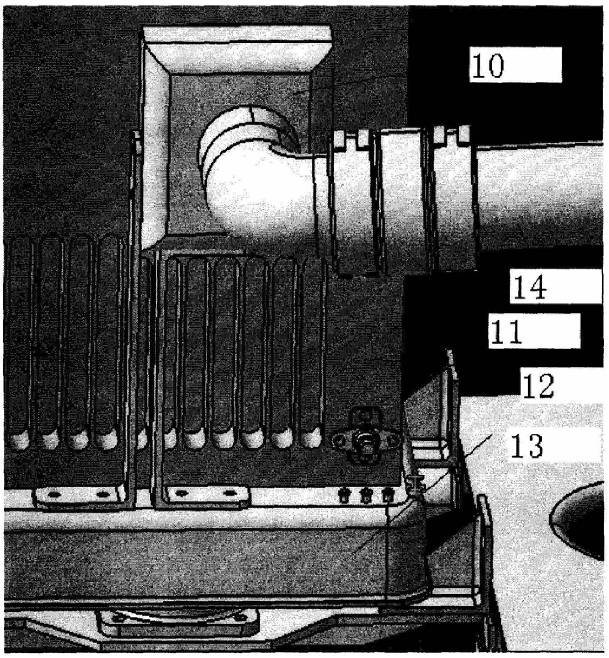
[0017] Referring to Fig. 3, it can be seen that the gas collecting hood 10 and the equipment 12 are moved on the shock absorbing base 13. Ram air cooling
Login to View More PUM
 Abstract
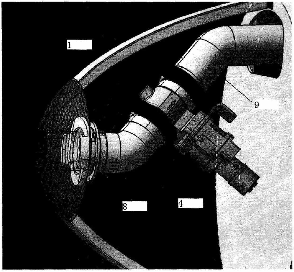
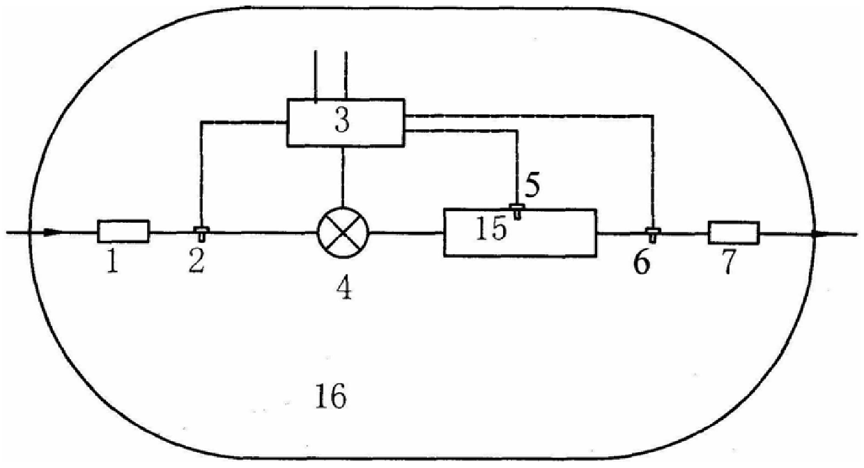
The invention relates to a ventilation and cooling device for an electronic pod. A ventilation inlet is opened in front of the pod to connect to the air inlet of the air-conditioning vehicle joint on the ground through a pipeline. The ventilation inlet is conformal to the shape of the pod. Set an inlet temperature sensor and a conduit connected to the inlet of the flow regulating valve, the outlet of the flow regulating valve sends ventilation air to each equipment compartment through the conduit, and the shock absorbing base of each equipment compartment is provided with an air collecting hood connected by a hose Connected, and the gas collection hood is fastened on the cold plate of the temperature sensor equipment. The exhaust temperature sensor is installed between the cold plate outlet and the exhaust port of the equipment. The invention can not only reduce the resistance of the pod, facilitate ground detection and debugging, prevent sand and foreign matter from entering the pod, but also isolate the vibration of the pod without requiring the ventilation and cooling device of the electronic pod that consumes other energy sources on the machine. Fixed an issue where the vent line did not match the electronics cold plate interface.
Description
Electronic Pod Ventilation and Cooling Device Technical Field [0001] The present invention relates to a ventilation cooling device widely used in various electronic pods. Background technique: Ventilation cooling device is a kind of commonly used device of pod electronic equipment cooling at present, and its principle is to utilize aircraft high-speed During flight, the ram air outside the aircraft is the cooling source, which provides ventilation and cooling for the electronic equipment of the pod. Ventilation cooling unit ventilates through its The air inlet introduces external ram air, according to the temperature value of the temperature sensor, according to the preset control law of the temperature control box, through Adjust the opening of the valve by adjusting the force, control the air flow into the cold plate of the equipment, and make the equipment work in a certain temperature range. inside. Domestic pod ventilation and cooling devices generally use cat e...
Claims
Login to View More Application Information
Patent Timeline
 IPC IPC(8): B64B1/22
Inventor 晏涛
Owner CHENGDU AIRCRAFT INDUSTRY GROUP
Features
- R&D
- Intellectual Property
- Life Sciences
- Materials
- Tech Scout
- Unparalleled Data Quality
- Higher Quality Content
- 60% Fewer Hallucinations
Learn More Browse by: Latest US Patents, China's latest patents, Technical Efficacy Thesaurus, Application Domain, Technology Topic, Popular Technical Reports.
© 2025 PatSnap. All rights reserved.Legal|Privacy policy|Modern Slavery Act Transparency Statement|Sitemap|About US| Contact US: help@patsnap.com