
Multi-shaft high-speed numerically controlled lathe
A CNC lathe, high-speed technology, applied in other manufacturing equipment/tools, tool holders, manufacturing tools, etc., can solve the problems of low product processing accuracy, cumbersome and complicated processing process, increase processing error, etc., to avoid the cantilever being too long. , Improve production efficiency and machining accuracy, and avoid the effect of errors
- Summary
- Abstract
- Description
- Claims
- Application Information
AI Technical Summary
Problems solved by technology
Method used
Image

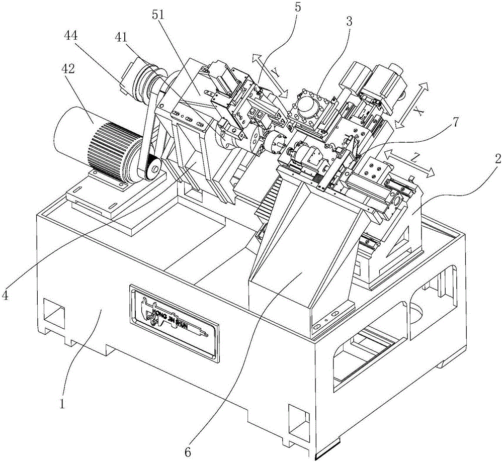
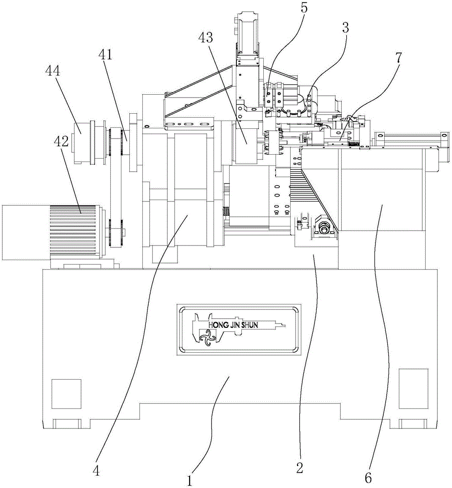
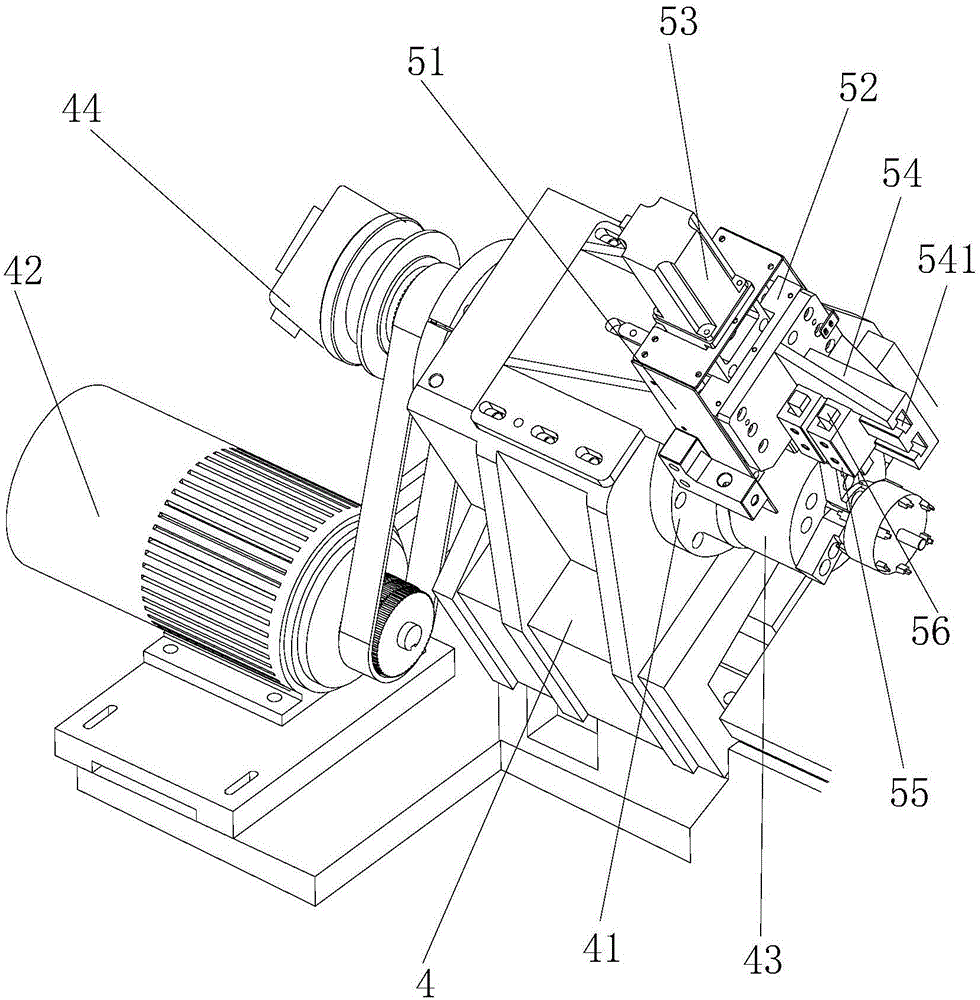
Examples
Embodiment Construction
[0019] The present invention will be further described below with reference to specific embodiments and accompanying drawings.
[0020] like Figure 1-Figure 5 As shown, the present invention is a multi-axis high-speed CNC lathe, which includes a lathe body with an inclined bed, and the lathe body with an inclined bed has a main table 1 and a working surface that is inclined to the main table 1 (usually 60° or 45°) inclined bed assembly 2, on the inclined bed assembly 2 is installed a first sliding table 21 (i.e. cross slide plate) and The first sliding table driving mechanism, the second sliding table 22 (ie the X-axis carriage) and the second sliding table driving mechanism 23 are installed on the first sliding table 21, and the second sliding table is on the first sliding table 21 along the same The vertical direction of the inclined bed assembly 2 is the X-axis movement; a four-station electric tool rest 3 is installed on the second sliding table, and a spindle box 4 is i...
PUM
 Abstract
Description
Claims
Application Information