Weldment stacking rack with lifting function

A technology of welding parts and functions, applied in the field of welding parts stacking racks, can solve problems such as safety accidents, operator's finger rolling, increasing the difficulty of the operator's work, etc., to reduce work intensity, facilitate transfer, and save manpower Effect

Inactive Publication Date: 2017-03-22
付建军
0 Cites 2 Cited by

AI-Extracted Technical Summary

Problems solved by technology

However, since there is almost no gap between adjacent weldments, the stacked weldments increase the difficulty of the operator's work during the tran...

Method used

As preferably, adopt elastic rubber roller, and then reduce the wearing and tearing of weldment front end when moving in rectangular groove 7, and the elastic rubber outer wall of cam 2 can take place certain deformation when its enlarged end contacts with weldment front end surface, In turn, a force that squeezes the outer wall of ...

Abstract

The invention discloses a weldment stacking rack with a lifting function. The weldment stacking rack with the lifting function comprises a supporting frame. A stand column A and a stand column B are arranged on the two long sides of the supporting frame separately. A plurality of rectangular grooves are formed in the inner side wall of the stand column A. The two side walls of the middle of each rectangular groove are each provided with a movable cavity. Cams are rotationally arranged in the movable cavities, and part of each cam is arranged in the corresponding rectangular groove in a protruding mode. A plurality of protrusions are arranged on the inner side wall of the stand column B at equal intervals. Balls are rotationally arranged on the upper end face and the lower end face of each protrusion. During shifting or application of weldments, the multiple weldments can be dragged at will or sequentially in the direction of clamping grooves, under the action of tensile force, the front ends of the weldments move in the rectangular grooves, and the two cams rotate reversely and simultaneously, that is to say, the expanded ends of the cams move away from each other gradually, so that enough space is provided for the front ends of the weldments to move outwards in the rectangular grooves, the tail ends of the weldments move fast under rotation support of the balls in the clamping grooves, and the work intensity of operators is relieved.

Application Domain

Technology Topic

Image

  • Weldment stacking rack with lifting function
  • Weldment stacking rack with lifting function

Examples

  • Experimental program(1)

Example Embodiment

[0019] Example 1
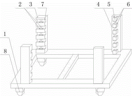
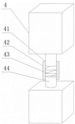
[0020] Such as figure 1 with figure 2 As shown, this embodiment includes a rectangular support frame 1. On two long sides of the support frame 1, there are uprights A3 and B4 spaced apart from each other, and a plurality of uprights are provided on the inner side wall of the upright A3. The support frame 1 has a rectangular groove 7 with parallel long sides, and a semi-spherical movable cavity is respectively provided on the two side walls in the middle of the rectangular groove 7, and the cam 2 is rotatably arranged in the movable cavity, and a part of the cam 2 protrudes Is placed in the rectangular groove 7; a plurality of protrusions 5 on the same vertical line are arranged at equal intervals on the inner side wall of the column B4, and balls 6 are rotatably arranged on the upper and lower ends of the protrusions 5, the The column B4 is composed of a supporting end and an adjusting end. The supporting end is fixed on the long side of the supporting frame 1, and the upper end surface of the supporting end is fixed with a threaded connecting rod 44, and the lower end surface of the adjusting end is fixed with a threaded extension rod 41, and The top end of the connecting rod 44 and the end of the extension rod 41 are respectively threadedly connected to the sleeve 42 and further includes a spring 43 placed in the sleeve 42. The two ends of the spring 43 are connected to the top end of the connecting rod 44 and the extension rod 41 respectively. End connection.
[0021] The specific operation is as follows: push the front end of the weldment along the plurality of clamping grooves formed on two mutually parallel uprights B4. The upper and lower surfaces of the protrusion 5 are rotatably provided with balls 6, using the balls 6 and the outer wall of the weldment. The rolling friction contact makes the weldment move quickly in the clamping groove until the front end of the weldment moves into the rectangular groove 7 and comes into contact with the two cams 2. The two cams 2 on the side wall of the rectangular groove 7 The direction of rotation is opposite, that is, as the front end of the weldment moves, the enlarged ends of the two cams 2 contact the outer wall of the weldment until the front end of the weldment is stuck between the two cams 2 and cannot continue to move, that is, The two long sides of the weldment are completely placed and fixed in the rectangular groove 7 and the clamping groove, and are counted from top to bottom. The level of the clamping groove is slightly larger than that of the rectangular groove 7, which makes the welding The parts are placed obliquely on the support frame 1 to ensure the stability of the weldment when placed, so that it will not slip out of the clamping range formed by the two uprights A3 and two uprights B4; when transferring the weldment Or when in use, multiple weldments can be pulled arbitrarily or sequentially from the direction of the clamping groove. Under the action of pulling force, the front end of the weldment moves in the rectangular groove 7, and the two cams 2 rotate in reverse at the same time. That is, the enlarged end of the cam 2 gradually moves away, so that the front end of the weldment in the rectangular groove 7 has enough space to move outward, and the end of the weldment moves quickly under the rotation support of the ball 6 in the clamping groove, so as to reduce welding. The strength of the parts pulling outwards reduces the work intensity of the operator. Further, the height of the clamping part of the column B4 in this embodiment can be adjusted, that is, the best tilted state is ensured according to the specific shape of the weldment, so as to avoid the placement of the weldment on the support frame 1 from loosening. , By rotating the sleeve 42 threadedly connected with the extension rod 41 and the connecting rod 44 to increase or decrease the distance between the end of the extension rod 41 and the top end of the connecting rod 44, thereby adjusting the lifting of the clamping part of the column B4 , And then reach to improve the scope of use of the device; and a spring 43 is installed between the top end of the connecting rod 44 and the end of the extension rod 41, the spring 43 can eliminate the axial runout stress generated when the weldment is placed or removed, Improve the service life of column B4.
[0022] Preferably, elastic rubber rollers are used to reduce the wear when the front end of the weldment moves in the rectangular groove 7, and the elastic rubber outer wall of the cam 2 can deform to a certain extent when its enlarged end is in contact with the front end of the weldment. The force of squeezing the outer wall of the weldment improves the stability of the weldment when placed at an angle.
[0023] Preferably, a plurality of universal wheels 8 are installed at the bottom of the support frame 1 to facilitate the transfer of weldments in large quantities, save manpower, and improve the work efficiency of operators.

PUM

no PUM

Description & Claims & Application Information

We can also present the details of the Description, Claims and Application information to help users get a comprehensive understanding of the technical details of the patent, such as background art, summary of invention, brief description of drawings, description of embodiments, and other original content. On the other hand, users can also determine the specific scope of protection of the technology through the list of claims; as well as understand the changes in the life cycle of the technology with the presentation of the patent timeline. Login to view more.

Similar technology patents

Classification and recommendation of technical efficacy words

  • Reduce work intensity
  • Reduce intensity

Intelligent answering method and system

InactiveCN104679910AImprove Smart Reply AccuracyReduce work intensitySpecial data processing applicationsAlgorithmDegree of similarity
Owner:BEIJING ZHICHI BOCHUANG TECH

Fiber opener

InactiveCN102586956AReduce work intensityReduce equipment costFibre cleaning and opening machine combinationsFibre cleaning/opening machinesEngineeringStructural engineering
Owner:常熟市伟成非织造成套设备有限公司

Dimming mirror with blind zone sub-mirror and indicator

ActiveUS6919796B2Reduce light intensityReduce intensityMirrorsAnti-collision systemsComputer visionWing mirror
Owner:MAGNA MIRRORS OF AMERICA
Why Eureka
Try Eureka