
Automatic initial rainwater interception type rainwater inlet device

A rainwater inlet and automatic technology, applied in water supply installations, waterway systems, drainage structures, etc., can solve the problems of siltation and blockage, polluting the receiving water body of urban rainwater pipeline system, etc., to reduce the possibility, reduce maintenance workload, and reduce maintenance. effect of difficulty

Active Publication Date: 2017-03-22
WUHAN MUNICIPAL ENG DESIGN & RES INST
View PDF7 Cites 11 Cited by
  • Summary
  • Abstract
  • Description
  • Claims
  • Application Information

AI Technical Summary

Problems solved by technology

The initial rainwater of each rainfall (abbreviation: initial rain) will carry a large amount of dust in the air and dissolve various polluting gases in the air during the process of falling to the ground in the air, and the rainwater will flow into the rainwater outlet after falling to the ground During the process, the suspended solids and slag on the ground will be taken away. Therefore, the primary rainwater generally contains a large amount of pollutants and suspended solids. Since the traditional gullies do not have any primary rain interception function, that is, for the initial rain The incoming water in the whole process of rainfall is collected and transported to the urban rainwater pipeline system without interception. However, actual engineering cases show that the initial rain will not only pollute the downstream of the urban rainwater pipeline system because of its high content of pollutants and suspended solids. At the same time, it will also lead to the silting and blockage of the urban rainwater pipeline system. In order to reduce the adverse impact on the water environment of the receiving water body and reduce the maintenance workload of the urban rainwater pipeline system, it is necessary to start from the beginning of the urban rainwater pipeline system - rainwater Interception of primary rain

Method used


Image

  • Automatic initial rainwater interception type rainwater inlet device
  • Automatic initial rainwater interception type rainwater inlet device

Examples


Embodiment Construction

[0030] The principles and features of the present invention are described below in conjunction with the accompanying drawings, and the examples given are only used to explain the present invention, and are not intended to limit the scope of the present invention.

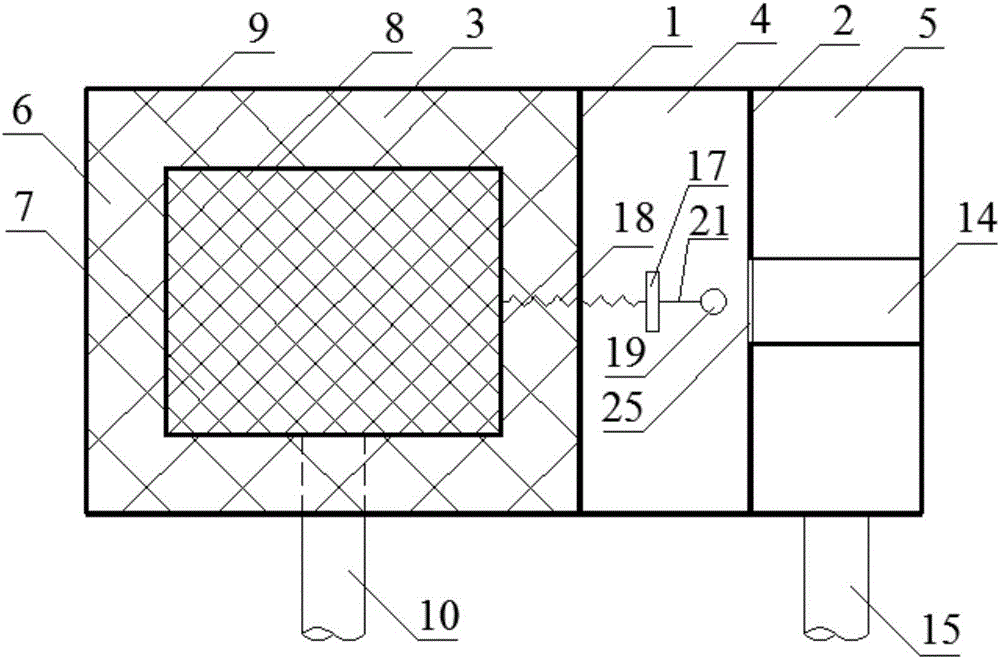
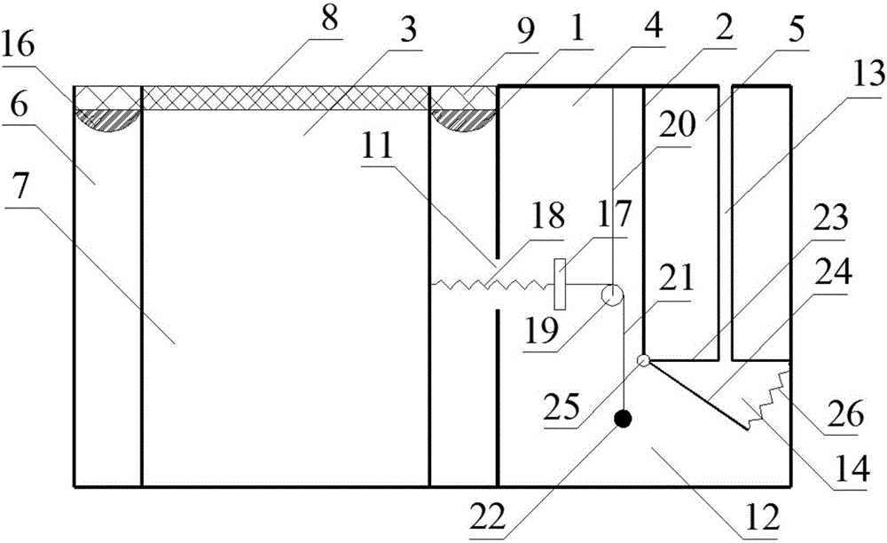
[0031] Such as figure 1 and 2 As shown, a first rain automatic interception type gully device includes a well chamber and a well top cover, and the first partition plate 1 and the second partition plate 2 are arranged at intervals in the well chamber, and the first partition plate 1 and the second partition plate The second partition 2 partitions the well from one side to the other into a main well 3 , a secondary well 4 and a discharge well 5 .

[0032] In the present embodiment, the well chamber is surrounded by five outer plates and the well top cover into a cuboid, and the inside is divided into three well chambers by vertical first partitions 1 and second partitions 2. The first partition 1 and the second par...


PUM


Abstract

The invention relates to an automatic initial rainwater interception type rainwater inlet device. The device comprises a well chamber and a well top cover, and a first partition plate and a second partition plate are arranged at an interval in the well chamber and partition the well chamber into a main well chamber, an auxiliary well chamber and a discharge well chamber from one side to the other side. The automatic initial rainwater interception type rainwater inlet device has advantages that additional arrangement of electric start-stop and control equipment is avoided, effectiveness in automatic interception of rainwater at an initial stage of rainfall is realized, and the initial rainwater is sent to a sewage treatment plant through an urban sewage pipeline system to realize treatment, so that adverse influences of the initial rainwater on downstream rainwater receiving water environment are reduced, probability of dregs and suspension sediments in a urban rainwater pipeline system is lowered, and maintenance workload of the urban rainwater pipeline system is relieved.

Description

technical field [0001] The invention relates to the technical field of municipal drainage facilities, in particular to an automatic intercepting gully device for early rain. Background technique [0002] The traditional urban rainwater pipeline system collects rainwater from the road through the rainwater outlet and then flows it into the main rainwater pipe or main pipe, and finally discharges it into the downstream receiving water body. Therefore, the rainwater outlet is the beginning and the most important part of the entire urban rainwater pipeline system. For facilities that collect rainwater from road surfaces, the quality of the collected road surface rainwater will directly affect the operation of the entire urban rainwater pipeline system. The initial rainwater of each rainfall (abbreviation: initial rain) will carry a large amount of dust in the air and dissolve various polluting gases in the air during the process of falling to the ground in the air, and the rainw...

Claims


Application Information

Patent Timeline
Patent Type & Authority Applications(China)
IPC IPC(8): E03F5/04E03F5/06E03F5/10
CPCE03F5/0401E03F5/0404E03F5/06E03F5/10E03F5/105E03F5/107E03F2201/10
Inventor 曾祥英李尔明丹
Owner WUHAN MUNICIPAL ENG DESIGN & RES INST
Learn More