Integrated wellhead continuous dosing device

A kind of dosing device and integrated technology, which is applied in the direction of wellbore/well parts, cleaning equipment, earthwork drilling and mining, etc., can solve the problems of cumbersome construction procedures for well washing operations, hidden dangers of wellhead safety, complex mechanical structures, etc., and achieve improved metering Accuracy, reduced failure rate, high transmission efficiency

Active Publication Date: 2017-03-22
DONGHAO MECHANICAL & ELECTRONICS
View PDF8 Cites 10 Cited by
  • Summary
  • Abstract
  • Description
  • Claims
  • Application Information

AI Technical Summary

Problems solved by technology

[0002] After drilling to find oil in the oil field, it is necessary to install a recovery machine to extract the crude oil in the well. In the extraction of crude oil, with the extraction of crude oil, a large amount of colloidal asphaltenes will be precipitated in the wellbore, which will block the oil pipe and affect oil recovery. , at this time, it is necessary to carry out well washing operations, and the construction procedures of well washing operations are cumbersome, costly, and pollute the environment
The anti-scaling operation is low in cost, safe and reliable. The anti-scaling operation needs to use a dosing device, which is connected with the medicine box and the wellhead annulus respectively, and injects the medicament into the wellhead annulus through a plunger pump. The prior art In the anti-scaling equipment, the dosing device at the wellhead has a complex mechanical structure. The return spring is set outside the pump body and is equipped with a shield. The shield is easy to rub against the pump body and generate sparks, which may cause hidden dangers at the wellhead. The return of key parts The position spring is arranged on the outside of the pump body, which is easy to contact with corrosive substances such as air to cause rust and corrosion damage, especially in the oil pumping wells in coastal areas with high air salt content and high humidity, and it is easy to be damaged. The sealing of the dosing device in the prior art is a packing seal, and the sealing performance is poor. At the same time, the drug absorption principle of the dosing device in the prior art is that the large plunger drives the small plunger to move through the hydraulic oil to absorb the medicine. The structure is complex and the transmission efficiency is low. Low

Method used


Image

  • Integrated wellhead continuous dosing device
  • Integrated wellhead continuous dosing device
  • Integrated wellhead continuous dosing device

Examples


Embodiment 1

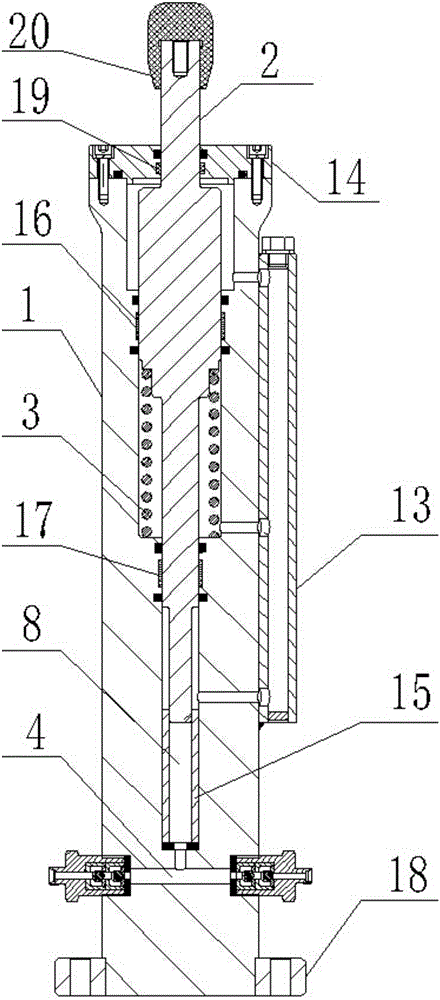
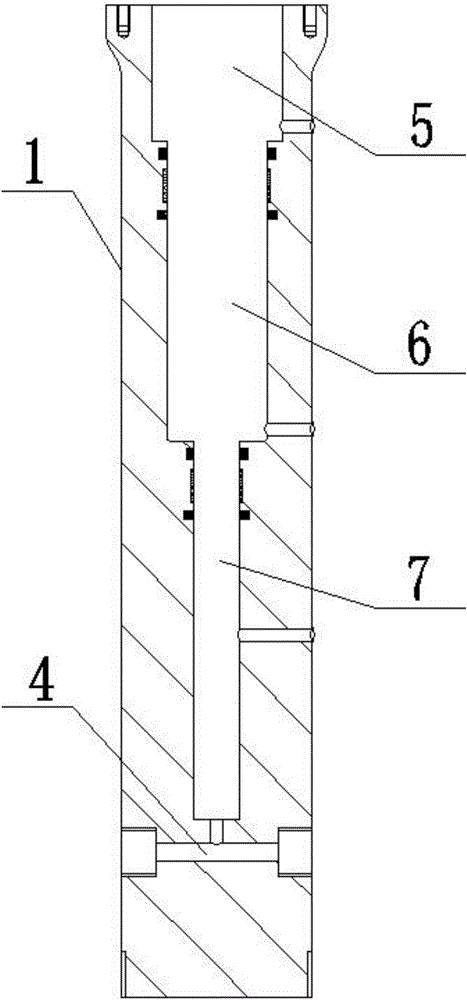
[0035] The integrated wellhead continuous dosing device has the advantages of simple structure, stable and reliable operation, strong environmental adaptability, accurate dosing amount, and convenient maintenance, such as figure 1 , image 3 As shown, it is specially set up as the following structure: including the power end and the flow end that are connected to each other; The top of the protruding end is in intermittent impact contact with the pressure plate on the polished rod of the oil extraction machine that reciprocates up and down, and a compression spring 3 that can return the plunger 2 is arranged between the chamber and the plunger 2; Chamber, drug box and wellhead annulus communicate with the flow channel 4, the flow channel 4 is opened inside the cylinder body 1. Wherein, an inlet check valve is screw-connected at the end of the flow channel 4 communicating with the medicine box, and an outlet check valve is screw-connected at the end of the flow channel 4 commu...

Embodiment 2

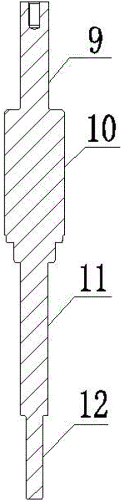
[0037] This embodiment is further optimized on the basis of the above-mentioned embodiments, in order to better realize the present invention, as figure 1 , figure 2 , image 3 As shown, the following arrangement structure is adopted in particular: the chamber includes the second chamber 6 and the third chamber 7 which are sequentially connected from top to bottom and whose inner diameters are successively reduced; The first rod part 10 and the second rod part 11 are connected and their outer diameters are successively reduced; an annular space is formed between the second chamber 6 and the second rod part 11, and the compression spring 3 is arranged in the annular space and its The top and the bottom respectively abut against the bottom of the first rod part 10 and the bottom surface of the second chamber 6 . Wherein, the second rod portion 11 is provided with a positioning block for positioning the compression spring 3, the positioning block is located at the junction of ...

Embodiment 3

[0039] This embodiment is further optimized on the basis of any of the above embodiments, in order to better realize the present invention, such as figure 1 , image 3 As shown, the following arrangement structure is adopted in particular: a lubricating oil communication radiator 13 with an internal oil passage is arranged on the outer wall of the cylinder body 1, and the lubricating oil communication radiator 13 can be disassembled and replaced from the cylinder body 1 to lubricate The oil communication radiator 13 communicates with the second chamber 6 , and oil is filled in the oil channel of the lubricating oil communication radiator 13 and the second chamber 6 . Wherein, the top of lubricating oil Unicom radiator 13 is provided with oil filling hole, and the oil filling hole is provided with oil filling hole screw plug, and the bottom of described lubricating oil Unicom radiator 13 is opened with oil drain hole, and oil drain hole is provided with oil drain screw plug.


PUM


Abstract

The invention discloses an integrated wellhead continuous dosing device which comprises a power end and an overflowing end in mutual connection with each other, wherein the power end comprises a cylinder and a plunger; the cylinder is vertically arranged; the plunger is inserted into a chamber of the cylinder; an extending end of the plunger is connected with a power source; a compression spring for resetting the plunger is arranged between the chamber and the plunger; the overflowing end comprises a channel which is respectively in annular communication with the chamber, a drug kit and a wellhead. Compared with the prior art, the integrated wellhead continuous dosing device has the advantages of simple structure, stability and reliability in work, high adaptive capacity to environment, accurate dosage and convenience in maintenance and repairing.

Description

technical field [0001] The invention relates to the field of petrochemical equipment, in particular to an integrated wellhead continuous dosing device. Background technique [0002] After drilling to find oil in the oil field, it is necessary to install a recovery machine to extract the crude oil in the well. In the extraction of crude oil, with the extraction of crude oil, a large amount of colloidal asphaltenes will be precipitated in the wellbore, which will block the oil pipe and affect oil recovery. , At this time, it is necessary to carry out well washing operation, and the construction process of well washing operation is cumbersome, the cost is high, and the environment is polluted. The anti-scaling operation is low in cost, safe and reliable. The anti-scaling operation needs to use a dosing device, which is connected with the medicine box and the wellhead annulus respectively, and injects the medicament into the wellhead annulus through a plunger pump. The prior art...

Claims


Application Information

Patent Timeline
Patent Type & Authority Applications(China)
IPC IPC(8): E21B37/06
CPCE21B37/06
Inventor 汪红科王林萝岗司文喜张培栓郭强
Owner DONGHAO MECHANICAL & ELECTRONICS
Why Eureka
Try Eureka