Integrated wellhead continuous dosing device
A dosing device, an integrated technology, applied in wellbore/well components, earthwork drilling, cleaning tools, etc., can solve problems such as cumbersome construction procedures for well cleaning, hidden safety hazards at wellheads, complex mechanical structures, etc., to improve metering. Accuracy, reduced failure rate, high transmission efficiency
- Summary
- Abstract
- Description
- Claims
- Application Information
AI Technical Summary
Problems solved by technology
Method used
Image
Examples
Embodiment 1
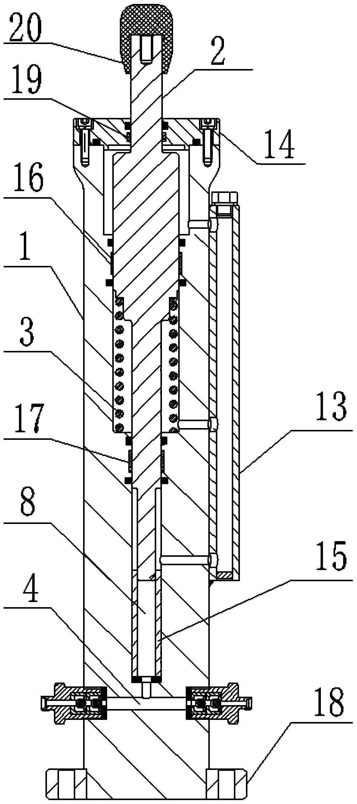
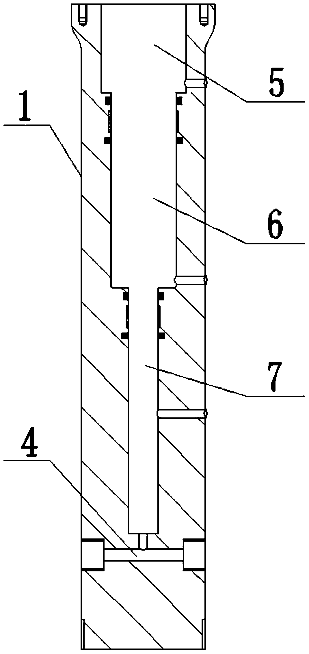
[0035] The integrated wellhead continuous dosing device has the advantages of simple structure, stable and reliable operation, strong environmental adaptability, accurate dosing amount, and convenient maintenance, such as figure 1 , image 3 As shown, it is specially set up as the following structure: including the power end and the flow end that are connected to each other; The top of the protruding end is in intermittent impact contact with the pressure plate on the polished rod of the oil extraction machine that reciprocates up and down, and a compression spring 3 that can return the plunger 2 is arranged between the chamber and the plunger 2; Chamber, drug box and wellhead annulus communicate with the flow channel 4, the flow channel 4 is opened inside the cylinder body 1. Wherein, an inlet check valve is screw-connected at the end of the flow channel 4 communicating with the medicine box, and an outlet check valve is screw-connected at the end of the flow channel 4 commu...
Embodiment 2
[0037] This embodiment is further optimized on the basis of the above-mentioned embodiments, in order to better realize the present invention, as figure 1 , figure 2 , image 3 As shown, the following arrangement structure is adopted in particular: the chamber includes the second chamber 6 and the third chamber 7 which are sequentially connected from top to bottom and whose inner diameters are successively reduced; The first rod part 10 and the second rod part 11 are connected and their outer diameters are successively reduced; an annular space is formed between the second chamber 6 and the second rod part 11, and the compression spring 3 is arranged in the annular space and its The top and the bottom respectively abut against the bottom of the first rod part 10 and the bottom surface of the second chamber 6 . Wherein, the second rod portion 11 is provided with a positioning block for positioning the compression spring 3, the positioning block is located at the junction of ...
Embodiment 3
[0039] This embodiment is further optimized on the basis of any of the above embodiments, in order to better realize the present invention, such as figure 1 , image 3 As shown, the following arrangement structure is adopted in particular: a lubricating oil communication radiator 13 with an internal oil passage is arranged on the outer wall of the cylinder body 1, and the lubricating oil communication radiator 13 can be disassembled and replaced from the cylinder body 1 to lubricate The oil communication radiator 13 communicates with the second chamber 6 , and oil is filled in the oil channel of the lubricating oil communication radiator 13 and the second chamber 6 . Wherein, the top of lubricating oil Unicom radiator 13 is provided with oil filling hole, and the oil filling hole is provided with oil filling hole screw plug, and the bottom of described lubricating oil Unicom radiator 13 is opened with oil drain hole, and oil drain hole is provided with oil drain screw plug.
PUM
 Abstract
Description
Claims
Application Information
 - R&D
- Intellectual Property
- Life Sciences
- Materials
- Tech Scout
- Unparalleled Data Quality
- Higher Quality Content
- 60% Fewer Hallucinations
Browse by: Latest US Patents, China's latest patents, Technical Efficacy Thesaurus, Application Domain, Technology Topic, Popular Technical Reports.
© 2025 PatSnap. All rights reserved.Legal|Privacy policy|Modern Slavery Act Transparency Statement|Sitemap|About US| Contact US: help@patsnap.com


