Cooling device of motorcycle cylinder

A technology for cooling devices and motorcycles, which is applied to cylinders, cylinder heads, engine components, etc. It can solve the problems of lower production efficiency, easy aging of sealing rings, and high energy consumption when cooling down, so as to improve work efficiency, avoid cylinder failures, The effect of prolonging the service life

Inactive Publication Date: 2017-03-22
范广志
View PDF1 Cites 4 Cited by
  • Summary
  • Abstract
  • Description
  • Claims
  • Application Information

AI Technical Summary

Problems solved by technology

[0002] The cylinder uses compressed air to work, and the temperature of the compressed air itself as the power source is greatly increased. After the compressed air enters the cylinder, the gas in the cylinder is continuously compressed and released due to the continuous reciprocating motion of the piston of the cylinder, generating heat, and then Coupled with the frictional heat generated by the piston movement of the cylinder, the temperature of the compressed air inside the cylinder will gradually become higher and higher. With the increase of the internal temperature of the cylinder, it exceeds the heat-resistant temperature of the cylinder sealing ring, making the cylinder at an ultra-high temperature The sealing ring is easy to age and fail when working down, so that there will be air leakage inside the cylinder, the cylinder will leak air, the thrust in the cylinder will be greatly reduced, and the use requirements cannot be met, and the cylinder cannot work normally
If the sealing ring of the cylinder is replaced, it will not only affect the continuity of production, but also reduce production efficiency and waste a lot of manpower maintenance costs
[0003] Most of the existing motorcycles use the method of cooling from the outside of the cylinder, the cooling effect is limited, and the conventional refrigerator is used to cool the cylinder, this kind of cooling consumes a lot of energy and the cooling effect is not good, so we propose a motorcycle Cooling device for car cylinder

Method used


Image

  • Cooling device of motorcycle cylinder
  • Cooling device of motorcycle cylinder

Examples


Embodiment Construction

[0014] The following will clearly and completely describe the technical solutions in the embodiments of the present invention with reference to the accompanying drawings in the embodiments of the present invention. Obviously, the described embodiments are only some, not all, embodiments of the present invention. Based on the embodiments of the present invention, all other embodiments obtained by persons of ordinary skill in the art without making creative efforts belong to the protection scope of the present invention.

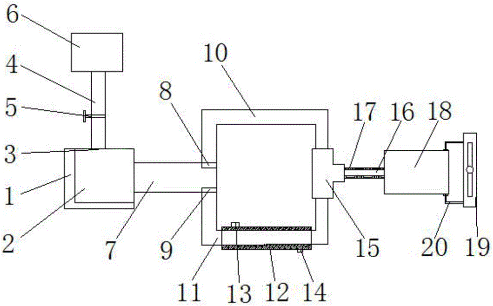
[0015] see Figure 1-2 , the present invention provides a technical solution: a cooling device for a motorcycle cylinder, comprising a vortex chamber 1 and a compressed air bag 6, the vortex chamber 1 is provided with a vortex generator 2, and the top of the vortex chamber 1 is provided with an air inlet 3 , the air inlet 3 is fixedly connected with the compressed air bag 6 through the air inlet pipe 4, the compressed air in the compressed air bag 6 has a conn...


PUM


Abstract

The invention discloses a cooling device of a motorcycle cylinder. The cooling device comprises a vortex chamber and a compressed air bag; a vortex generator is arranged in the vortex chamber; an air inlet is arranged on the top of the vortex chamber; the air inlet is fixedly connected with the compressed air bag through an air inlet pipe; a control valve is further arranged on the air inlet pipe; a vortex rectifier tube is also fixedly arranged on one side of the vortex chamber; a cool air outlet and a hot air outlet are separately arranged on two sides of the vortex rectifier tube; the cool air outlet and the hot air outlet are separately fixedly connected with an air inlet end of a cool air pipe and an air inlet end of a hot air pipe; and the outer surface of the hot air pipe is wrapped by a cooling clamping bag. The cooling device of the motorcycle cylinder is simple in structure and reasonable in design; the cylinder can be rapidly cooled in a safe and effective manner; service life of parts in the cylinder is prolonged; and working efficiency of the cylinder is effectively improved.

Description

technical field [0001] The invention relates to the technical field of motorcycle accessories, in particular to a cooling device for a motorcycle cylinder. Background technique [0002] The cylinder uses compressed air to work, and the temperature of the compressed air itself as the power source is greatly increased. After the compressed air enters the cylinder, the gas in the cylinder is continuously compressed and released due to the continuous reciprocating motion of the piston of the cylinder, generating heat, and then Coupled with the frictional heat generated by the piston movement of the cylinder, the temperature of the compressed air inside the cylinder will gradually become higher and higher. With the increase of the internal temperature of the cylinder, it exceeds the heat-resistant temperature of the cylinder sealing ring, making the cylinder at an ultra-high temperature The sealing ring is prone to aging and failure when working down, so that air leakage will occ...

Claims


Application Information

Patent Timeline
IPC IPC(8): F02F1/14F02F1/04
CPCF02F1/14F02F1/04
Inventor 范广志
Owner 范广志
Why Eureka
Try Eureka