Pressurization type liquid ring vacuum pump water return system with rotating film and water return method thereof

A liquid ring vacuum pump and vacuum pump technology are applied in the return water system of a pressurized liquid ring vacuum pump and the return water field of a pressurized liquid ring vacuum pump return water system, which can solve the problem that the temperature of the liquid ring is difficult to drop, the working condition of the vacuum pump is over-temperature, The problems such as the reduction of the pumping capacity, to achieve the effect of reducing the heat transfer end difference, reducing the temperature of the liquid ring, and reducing the resistance

Active Publication Date: 2017-03-22
CENT SOUTHERN CHINA ELECTRIC POWER DESIGN INST CHINA POWER ENG CONSULTING GROUP CORP
View PDF6 Cites 3 Cited by
  • Summary
  • Abstract
  • Description
  • Claims
  • Application Information

AI Technical Summary

Problems solved by technology

As a result, the temperature of the liquid ring is difficult to drop; in addition, if figure 2 As shown, the heat exchange equipment of the conventional return water system mostly uses external plate heat exchangers. This type of system layout is not compact, occupies a large area, is inconvenient for maintenance, and the heat exchange efficiency is not high. temperature, low working efficiency, reduced pumping capacity, cavitation and other problems

Method used


Image

  • Pressurization type liquid ring vacuum pump water return system with rotating film and water return method thereof
  • Pressurization type liquid ring vacuum pump water return system with rotating film and water return method thereof
  • Pressurization type liquid ring vacuum pump water return system with rotating film and water return method thereof

Examples


Embodiment Construction

[0037] The implementation of the present invention will be described in detail below in conjunction with the accompanying drawings, but they do not constitute a limitation to the present invention, and are only examples. At the same time, the advantages of the present invention are clearer and easier to understand through the description.

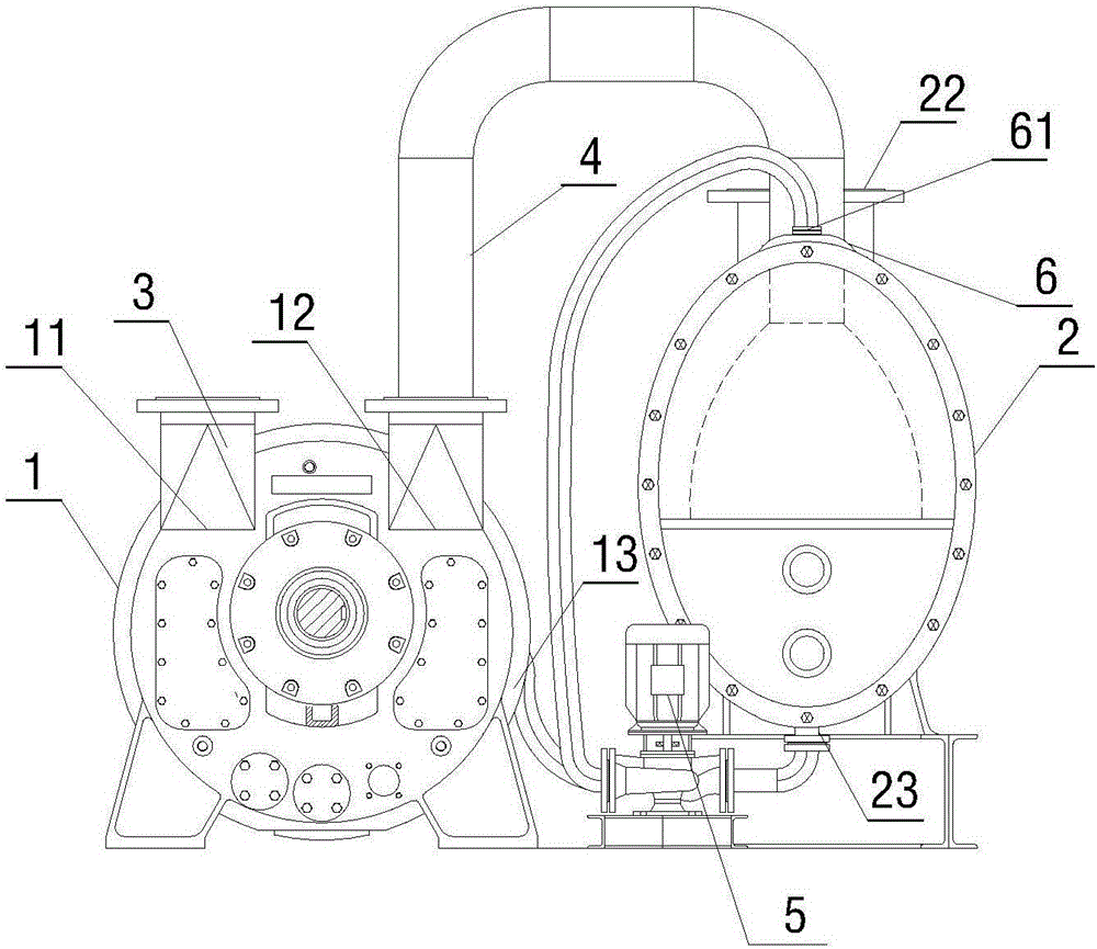
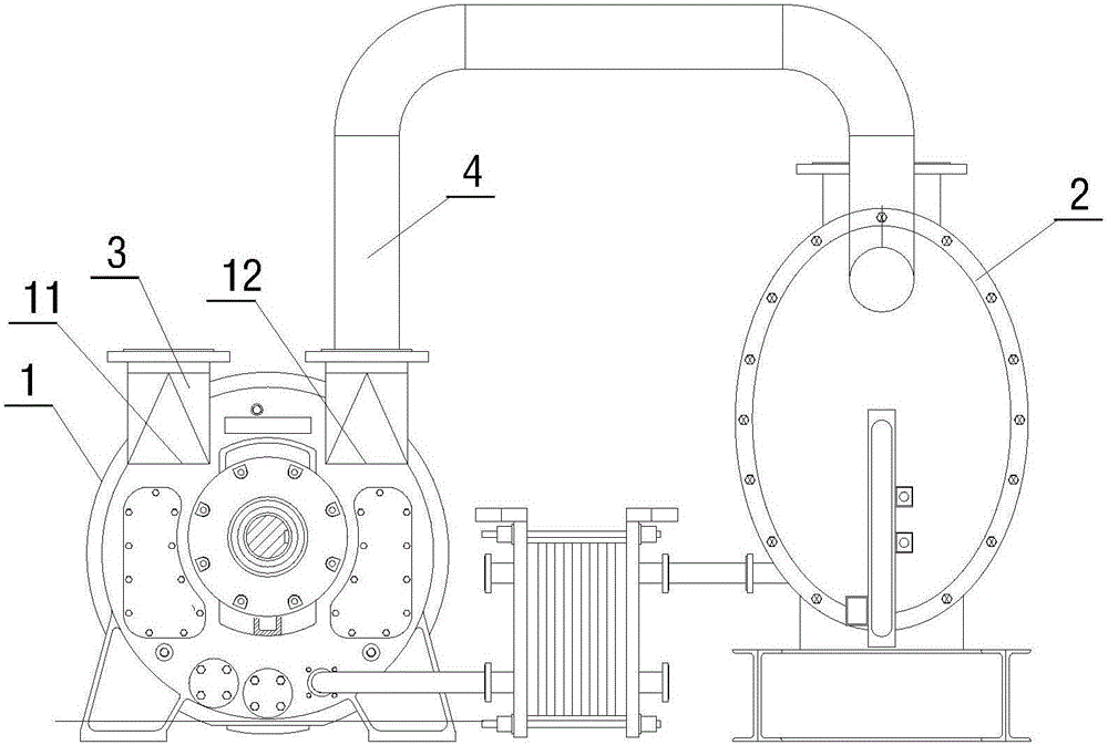
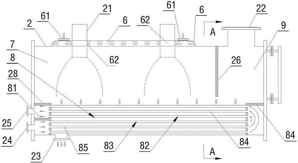
[0038] Referring to the accompanying drawings, it can be seen that the return water system of a pressurized liquid ring vacuum pump with a rotating membrane includes a vacuum pump body 1, a gas-water separator 2, an inlet material pipe 3 and an outlet material pipe 4; the upper end of the vacuum pump body 1 is provided with a pump body material inlet 11 and pump body material outlet 12, the lower end of the vacuum pump body 1 is provided with a water return port 13, the upper end of the gas-water separator 2 is provided with a separator material inlet 21 and a separated gas outlet 22, and the lower end of the gas-water separator 2 is provide...


PUM


Abstract

The invention discloses a pressurization type liquid ring vacuum pump water return system with a rotating film, and relates to the liquid ring vacuum pump water return system applied in the fields of chemical engineering, machinery, exploration, electric power and the like. The liquid ring vacuum pump water return system comprises a vacuum pump body, a vapor-water separator, a feeding pipe, a discharging pipe, a pressurization pump, a rotating film area, a cooling liquid inlet, a vapor-water separation area, a heat exchange area, a commutating area, a flow guide plate, a gas-phase passage and an annular separating plate, wherein a rotating film tube is installed in the rotating film area, and the tube wall of the rotating film tube is provided with rotating film holes; a heat exchange separating plate is installed in the heat exchange area, and a heat exchange liquid inlet communicates with a water inlet of a lower heat exchange pipe; a heat exchange liquid outlet communicates with a water outlet of an upper heat exchange pipe; and the input end of the pressurization pump communicates with a separating liquid outlet, and the output end of the pressurization pump communicates with a water return port and the cooling liquid inlet. By means of the pressurization type liquid ring vacuum pump water return system with the rotating film, water return fluid disturbance can be reduced, and resistance is lowered. The invention further relates to a water return method of the pressurization type liquid ring vacuum pump water return system with the rotating film.

Description

technical field [0001] The invention relates to a return water system of a liquid ring vacuum pump used in the fields of chemical industry, machinery, exploration, electric power and the like, in particular to a pressurized type liquid ring vacuum pump return water system with a spinning film. The invention also relates to the water return method of the pressurized liquid ring vacuum pump return water system with a spinning membrane. Background technique [0002] Liquid ring vacuum pumps are mainly used in the formation of rough vacuum. Because of their advantages of close to isothermal compression, insensitivity to dust, and the inhaled gas can entrain liquid or a large amount of water vapor, it is widely used in the power industry. Both the vacuum stage and the vacuum maintenance stage are completed using vacuum pumps and complete sets of units. The liquid ring vacuum pump is composed of a low-speed motor, gas-water separator, working fluid cooler, pneumatic control syste...

Claims


Application Information

Patent Timeline
Patent Type & Authority Applications(China)
IPC IPC(8): F04C19/00F04C29/00F04C29/04
CPCF04C19/004
Inventor 闵山山桂本徐传海裴龙匡云黄军军刘杰陈佳乐陈静
Owner CENT SOUTHERN CHINA ELECTRIC POWER DESIGN INST CHINA POWER ENG CONSULTING GROUP CORP
Why Eureka
Try Eureka