Oil supply and control device for hydraulic clutch

A technology of hydraulic clutches and control devices, applied in the direction of clutches, fluid-driven clutches, non-mechanical drive clutches, etc., to achieve the effects of ensuring stable meshing, improving pressure response speed, and stably transmitting torque

Active Publication Date: 2017-03-22
ZHEJIANG UNIV
View PDF4 Cites 6 Cited by
  • Summary
  • Abstract
  • Description
  • Claims
  • Application Information

AI Technical Summary

Problems solved by technology

[0005] The purpose of the present invention is to provide a large flow control device that can precisely control the

Method used


Image

  • Oil supply and control device for hydraulic clutch
  • Oil supply and control device for hydraulic clutch
  • Oil supply and control device for hydraulic clutch

Examples


Embodiment 1

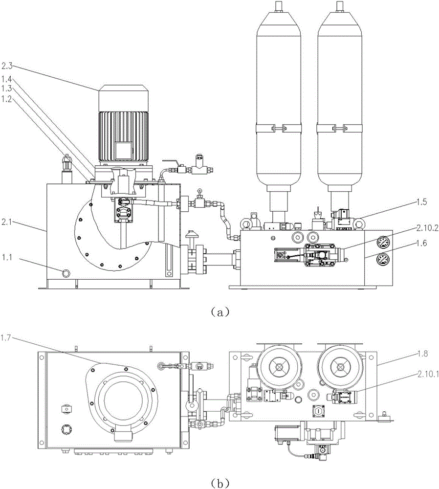
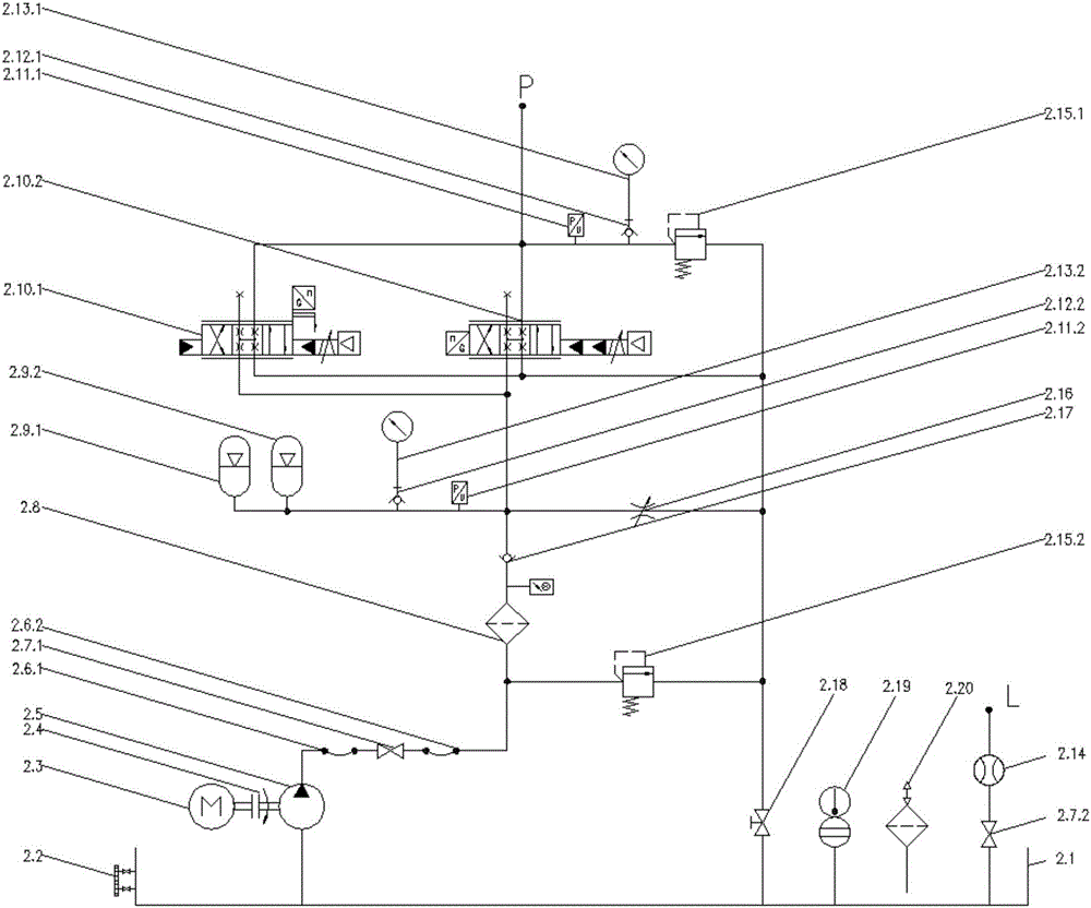
[0035] Embodiment 1: In this embodiment, the device includes a flow meter 2.14 installed on the second globe valve 2.7.2, a first accumulator 2.9.1, a second accumulator 2.9.2, and a second pressure sensor 2.11. 2. Second pressure measuring joint 2.12.2, second pressure gauge 2.13.2, throttle valve 2.16;

[0036] refer to figure 1 and figure 2 , when the device starts to work, the AC motor 2.3 starts to rotate, drives the hydraulic pump 2.5 to rotate, and the hydraulic pump 2.5 starts to supply oil, and the oil passes through the first hose 2.6.1, the first cut-off ball valve 2.7.1 and the second hose 2.6 .2 into the hydraulic control valve block. The oil is filtered through the filter 2.8, and then the first accumulator 2.9.1 and the second accumulator 2.9.2 are charged and pressure built up. The second overflow valve 2.15.2 is used to control the oil charging pressure of the accumulator, and the one-way valve 2.17 is used to prevent the return of pressure oil. The secon...


PUM


Abstract

The invention discloses an oil supply and control device for a hydraulic clutch. The oil supply and control device comprises a hydraulic pump station and a hydraulic control valve group. The hydraulic pump station comprises an oil tank, an alternating current motor, a hydraulic pump, an air filter, an electronic liquid level and temperature meter, an electronic liquid level meter, a liquid level and temperature meter, a liquid level meter, stop ball valves, a butterfly valve, a bell jar, a bell jaw gasket, a flange gasket, a damping ring, a coupler, a plug and hoses, wherein the bell jar, the bell jaw gasket, the flange gasket, the damping ring, the coupler, the plug and the hoses are used for connection. The hydraulic control valve group comprises a valve block, a valve block installation plate, a lifting lug bolt, a plug, a filter, a one-way valve, a servo valve, an overflow valve, a pressure measuring connector, an energy accumulator, a pressure sensor and a pressure gage. Rapid engagement and pressure control can be achieved for the hydraulic clutch by means of the oil supply and control device, and the oil supply and control device has the advantages of being large in instantaneous flow, accurate in pressure control and large in flow control range.

Description

technical field [0001] The invention relates to the field of hydraulic clutch engagement control, in particular to a hydraulic clutch oil supply and control device. Background technique [0002] With the development of heavy machinery and heavy ships in China, the demand for high-power transmission devices and their control devices is increasing. The hydraulic clutch is an important connection device that controls the power transmission of the shaft system, and is an important safety guarantee and speed control device on the power transmission chain. The torque transmitted by the hydraulic clutch is determined by the input torque in the fully meshed state, that is, when there is no relative rotation at both ends of the hydraulic clutch; while the hydraulic clutch is in the meshed state, that is, when there is relative rotation at both ends of the hydraulic clutch, the torque transmitted by it is on the one hand It is related to the input torque and on the other hand to the ...

Claims


Application Information

Patent Timeline
IPC IPC(8): F16D25/12F15B11/028
CPCF15B11/028F16D25/12
Inventor 王迪张军辉鲍静涵刘代峰
Owner ZHEJIANG UNIV
Why Eureka
Try Eureka