Smoke ultra-low emission purification equipment of coal-fired industrial boiler

An industrial furnace and coal-fired technology, applied in emission prevention, combustion methods, gas treatment, etc., can solve problems such as high pollutant emission intensity, backward combustion methods, and variable coal types

Active Publication Date: 2017-03-22
科林环保技术有限责任公司
View PDF20 Cites 4 Cited by
  • Summary
  • Abstract
  • Description
  • Claims
  • Application Information

AI Technical Summary

Problems solved by technology

[0002] At present, coal-fired industrial boilers have low combustion efficiency and high pollutant emission intensity due to various coal types, poor coal quality, deteriorating combustion, and backward combustion methods.

Method used


Image

  • Smoke ultra-low emission purification equipment of coal-fired industrial boiler
  • Smoke ultra-low emission purification equipment of coal-fired industrial boiler
  • Smoke ultra-low emission purification equipment of coal-fired industrial boiler

Examples


Embodiment 1

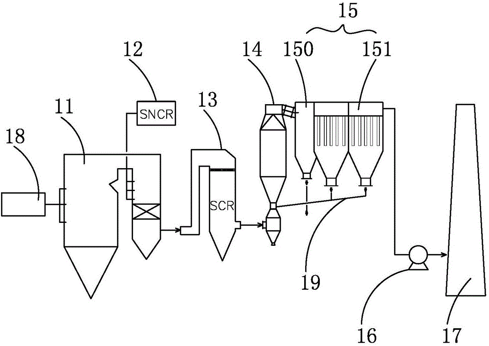
[0024] Such as figure 1 Shown is an ultra-low emission purification equipment for coal-fired industrial furnace flue gas. The SNCR denitration equipment 12 connected with the boiler 11, the SCR denitration equipment 13 connected with the flue gas outlet flue of the boiler 11, the semi-dry desulfurization equipment connected with the SCR denitration equipment 13, and the dust removal equipment connected with the semi-dry desulfurization equipment, The dust removal equipment is connected to the clean air outlet to discharge to the chimney 17, and the dust removal equipment and the chimney 17 are connected through an induced draft fan 16. The flue gas is desulfurized by calcium spraying in the furnace first, then denitrated by SNCR coupled with SCR, desulfurized by semi-dry method, and then discharged after dust removal. In this example:

[0025] According to the furnace temperature and structural conditions of coal-fired industrial boilers, especially the wide-area and large-s...

Embodiment 2

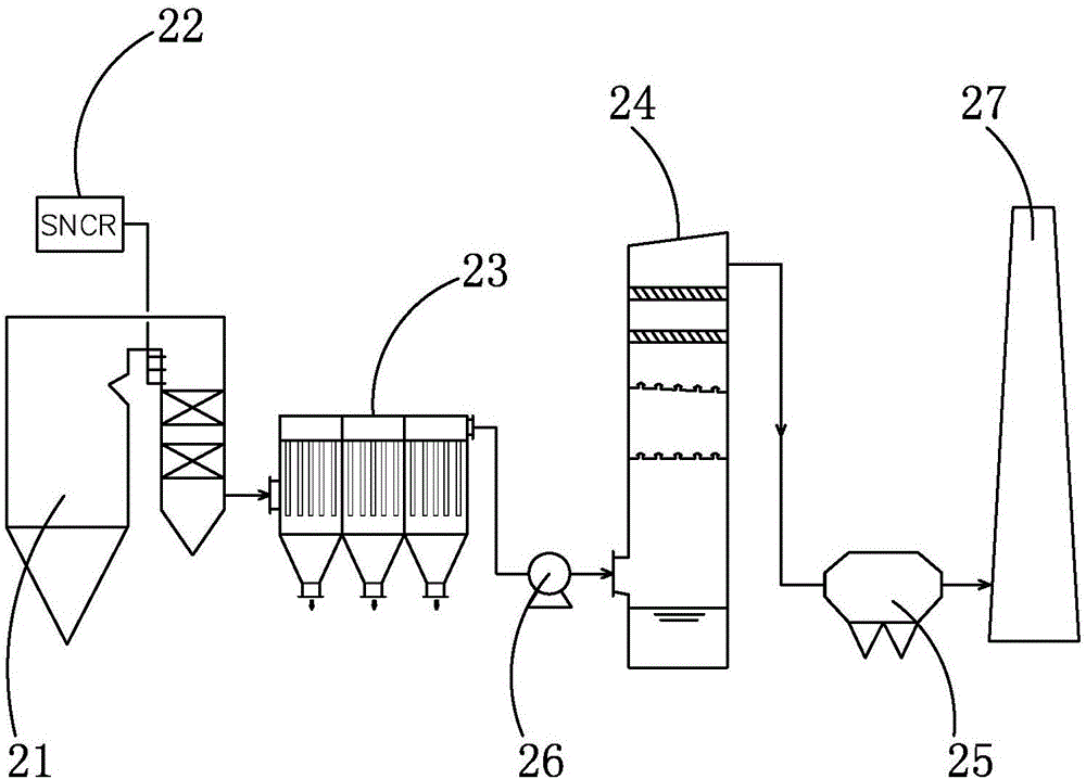
[0035] Such as figure 2 Shown is an ultra-low emission purification equipment for coal-fired industrial furnace flue gas. The dust collector equipment 23 connected with the dust collector equipment 23, the wet desulfurization and denitrification equipment connected with the dust collector equipment 23, the demist equipment 25 connected with the wet desulfurization and denitrification equipment, the demist equipment 25 is connected to the clean gas outlet to discharge to the chimney 27, and the dust collector equipment 23 It is connected with the desulfurization and denitrification equipment through the induced draft fan 26. After the flue gas is denitrated by SNCR, it is discharged after dust removal, desulfurization, further denitrification and demisting. In this example:

[0036] In view of the low and unstable furnace flue gas temperature of small and medium-sized coal-fired industrial boilers, SNCR denitrification equipment 22 adopts medium-temperature SNCR denitrificati...


PUM


Abstract

The invention relates to smoke ultra-low emission purification equipment of a coal-fired industrial boiler. The smoke ultra-low emission purification equipment of the coal-fired industrial boiler comprises SNCR denitrification equipment communicating with a boiler body, and a desulfurization and denitrification dust removal assembly communicating with a smoke outlet flue of the boiler. The sulfurization and denitrification dust removal assembly is connected with a purified air outlet. When the boiler is a medium-small coal-fired industrial boiler with unstable combustion and loads, the SNCR denitrification equipment is medium-temperature denitrification equipment, and the denitrification temperature is 500-800 DEG C. When the boiler is a medium-large coal-fired industrial boiler with stable combustion and loads, the SNCR denitrification equipment is high-temperature denitrification equipment, and the denitrification temperature is 800-1100 DEG C. The purification equipment can meet the ultra-low emission requirements that the smoke exhaust concentration is smaller than or equal to 5 mg / m<3>, the SO2 emission concentration is smaller than or equal to 35 mg / m<3>, and the NOx emission concentration is smaller than or equal to 50 mg / m<3>.

Description

technical field [0001] The invention relates to the field of flue gas purification treatment, in particular to ultra-low emission purification equipment for coal-fired industrial furnace flue gas. Background technique [0002] At present, coal-fired industrial boilers have low combustion efficiency and high pollutant emission intensity due to various coal types, poor coal quality, deteriorating combustion, and backward combustion methods. The annual flue gas emissions from coal-fired industrial furnaces contain high levels of sulfur dioxide, nitrogen oxides, dust, and waste residues. Dust removal, desulfurization, and denitrification must be performed on the flue gas. Although dust removal, desulfurization and denitrification equipment are diverse, how to achieve economical, efficient, and cost-effective has always required continuous research and progress. Contents of the invention [0003] The object of the present invention is to provide a coal-fired industrial furnace...

Claims


Application Information

Patent Timeline
Patent Type & Authority Applications(China)
IPC IPC(8): F23J15/02F23J15/04B01D53/75B01D53/60B01D53/96
CPCB01D53/60B01D53/75B01D53/96B01D2258/0283F23J15/006F23J15/02F23J15/027F23J15/04F23J2215/10F23J2217/40F23J2219/10F23J2219/20Y02A50/20
Inventor 徐天平沈强苟登军
Owner 科林环保技术有限责任公司
Why Eureka
Try Eureka