Combined flue gas denitrification system

A combined, flue gas technology, applied in separation methods, dispersed particle separation, chemical instruments and methods, etc., can solve problems such as wear and catalyst dust accumulation, reduce construction and operation costs, reduce operating costs, and control consumption Effect

Active Publication Date: 2018-12-25
JIANGSU YIJIN ENVIRONMENTAL PROTECTION TECH CO LTD
View PDF5 Cites 0 Cited by
  • Summary
  • Abstract
  • Description
  • Claims
  • Application Information

AI Technical Summary

Problems solved by technology

[0008] The purpose of the present invention is to overcome the deficiencies of the above technologies, thereby providing a combined flue gas denitrification system, which not only has a good denitrification effect, but also can well solve the problems of catalyst dust accumulation and wear.

Method used


Image

  • Combined flue gas denitrification system
  • Combined flue gas denitrification system
  • Combined flue gas denitrification system

Examples


Embodiment Construction

[0027] The present invention will be further described below in conjunction with the accompanying drawings and specific embodiments.

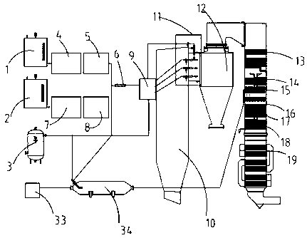
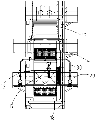
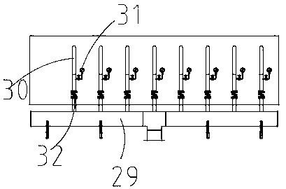
[0028] Such as Figure 1-Figure 5 As shown, the present invention discloses a combined flue gas denitrification system, which includes a desalinated water tank 1, an ammonia water storage tank 2, and a compressed air storage tank 3. 5 is connected to the static mixer 6, the ammonia water storage tank 2 is connected to the static mixer 6 through the ammonia water delivery module 7 and the ammonia water metering adjustment module 8, and the static mixer 6 and the compressed air storage tank 3 are connected to the distribution The modules 9 are connected, and the distribution module 9 is connected with an SNCR injection module 11, and the SNCR injection module 11 is arranged at the flue gas outlet of the boiler furnace 10, and the flue gas outlet of the boiler furnace 10 is connected with a cyclone separator 12 , the cyclone separator 12 is conne...


PUM


Abstract

The invention provides a combined type flue gas denitration system which comprises a desalted water tank, an ammonia water storage tank and a compressed air storage tank. The desalted water tank is connected with a static mixer by a desalted water delivering module and a desalted water metering and adjusting module, the ammonia water storage tank is connected with the static mixer by an ammonia water delivering module and an ammonia water metering and adjusting module, the static mixer is connected with the compressed air storage tank and a distributing module, an SNCR (selective non-catalytic reduction) spray module is connected with the distributing module and is arranged at a flue gas outlet of a hearth of a boiler, a cyclone separator is connected to the flue gas outlet of the hearth of the boiler, a tail heated device is connected with the cyclone separator and comprises a superheater, a high-temperature coal economizer, a flue gas flow guide device, ammonia spray grids, a catalysis module, a low-temperature coal economizer and an air preheater which are sequentially arranged from top to bottom, and the ammonia spray grids are connected with an ammonia gas generating mechanism. The combined type flue gas denitration system has the advantages that good denitration effects can be realized, and problems of dust accumulation, abrasion and the like of catalysts can be effectively solved.

Description

technical field [0001] The invention relates to a combined flue gas denitrification system. Background technique [0002] As one of the main substances that form acid rain and photochemical smog and destroy the ozone layer, NOx has strong toxicity and is extremely harmful to human body, environment and ecology. According to the data released by the National Environmental Protection Agency, the top three industries with NOx emissions are the production and supply of electricity and heat, the non-metallic mineral products industry, and the ferrous metal smelting and rolling processing industry, accounting for about 30% of the NOx emissions of the statistical industries. 81.4%. Among them, the production and supply of electricity and heat accounted for about 64.8%. [0003] At present and for a long period of time in the future, in the production and supply of electricity and heat with coal as the main energy source, NOx in the flue gas produced by the combustion of coal-fire...

Claims


Application Information

Patent Timeline
Patent Type & Authority Patents(China)
IPC IPC(8): B01D53/90B01D53/76B01D53/56
CPCB01D53/76B01D53/8631B01D53/90B01D2251/2062
Inventor 沈卫东陈砚雄谢慧王小飞蒙剑琼
Owner JIANGSU YIJIN ENVIRONMENTAL PROTECTION TECH CO LTD
Why Eureka
Try Eureka