System and method for ultralow discharge of boiler flue gas
A boiler flue gas and emission system technology, applied in chemical instruments and methods, separation methods, gas treatment, etc., can solve the problems of short service life of high-temperature SCR catalyst, increased denitration cost, and no mention of flue gas denitration treatment technology, etc. Achieve the effect of improving energy utilization efficiency, reducing denitration costs, and improving boiler thermal efficiency
- Summary
- Abstract
- Description
- Claims
- Application Information
AI Technical Summary
Problems solved by technology
Method used
Image
Examples
Embodiment 1
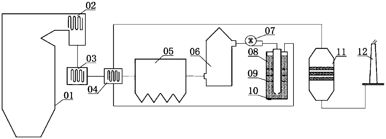
[0029] Such as figure 1 As shown, it is a schematic diagram of a boiler flue gas ultra-low emission system in this embodiment. The boiler flue gas ultra-low emission system includes a furnace 01, an economizer 02, an air preheater 03, a heat exchanger 04, and a dust collector 05. Desulfurization tower 06, induced draft fan 07, cleaning device 08, denitrification reactor 11 and chimney 12;
[0030] The furnace 01, the economizer 02, the air preheater 03, the heat exchanger 04, the dust collector 05, the desulfurization tower 06, the induced draft fan 07 and the cleaning device 08 connected in sequence; wherein, the heat exchanger 04 includes a first gas inlet for connecting with the air preheater 3 and a first gas outlet for connecting with the dust remover 05; the first gas The inlet and the first gas outlet are connected through a first flue gas pipe;
[0031] The heat exchanger 04 also includes a second gas inlet connected to the gas outlet of the cleaning device 08 and a ...
Embodiment 2
[0037] This embodiment provides a method for ultra-low emission of boiler flue gas, adopting the ultra-low emission system of boiler flue gas described in Embodiment 1; the method is:
[0038] The boiler flue gas first passes through the economizer 02, the air preheater 03 and the heat exchanger 04 and enters the dust collector 05 at a temperature of 130°C, the temperature of the flue gas exiting the dust collector 05 is 85°C, and the smoke concentration is 10mg / Nm 3 (In this embodiment, the dust collector 05 adopts a bag filter). The flue gas after dedusting enters the desulfurization tower 06, and the SO in the flue gas after desulfurization 2 The concentration is 14mg / Nm 3 , The temperature is 52 ℃. After desulfurization, the flue gas is sent to the cleaning device 08 by the induced draft fan 07, and the potassium hydroxide solution is used to further absorb the residual dust and SO 2, the dust concentration in the flue gas after cleaning is 2 mg / Nm 3 , SO 2 The concen...
Embodiment 3
[0040] This embodiment provides a method for ultra-low emission of boiler flue gas, adopting the ultra-low emission system of boiler flue gas described in Embodiment 1; the method is:
[0041] The boiler flue gas first passes through the economizer 02, the air preheater 03 and the heat exchanger 04 and enters the dust collector 05 at a temperature of 140°C, the temperature of the flue gas exiting the dust collector 05 is 90°C, and the smoke concentration is 12mg / Nm 3 (In this embodiment, the dust collector 05 adopts an electric bag dust collector). The flue gas after dedusting enters the desulfurization tower 06, and the SO in the flue gas after desulfurization 2 The concentration is 16mg / Nm 3 , The temperature is 54 ℃. After desulfurization, the flue gas is sent to the cleaning device 08 by the induced draft fan 07, and the sodium hydroxide solution is used to further absorb the residual dust and SO 2 , the dust concentration in the flue gas after cleaning is 2 mg / Nm 3 , ...
PUM
 Abstract
Description
Claims
Application Information
 - R&D
- Intellectual Property
- Life Sciences
- Materials
- Tech Scout
- Unparalleled Data Quality
- Higher Quality Content
- 60% Fewer Hallucinations
Browse by: Latest US Patents, China's latest patents, Technical Efficacy Thesaurus, Application Domain, Technology Topic, Popular Technical Reports.
© 2025 PatSnap. All rights reserved.Legal|Privacy policy|Modern Slavery Act Transparency Statement|Sitemap|About US| Contact US: help@patsnap.com

