High precision angle measurement system and method for spacecraft

A technology of angle measurement and measurement method, which is applied in theodolite and other directions, can solve problems such as low measurement efficiency, error accumulation, and influence on measurement accuracy, and achieve the effects of improving accuracy and stability, reducing error accumulation, and improving measurement efficiency

Inactive Publication Date: 2017-03-22
SHANGHAI INST OF SATELLITE EQUIP
View PDF5 Cites 17 Cited by
  • Summary
  • Abstract
  • Description
  • Claims
  • Application Information

AI Technical Summary

Problems solved by technology

[0004] First, the use of theodolite must be observed with human eyes. In the actual test process, it will be affected by factors such as different human eyesight, the distance of the target to be measured, and illumination. Especially when measuring for a long time, it is more likely to be affected by subjective factors, which affects the measurement. precision;
[0005] Second, there are many inter-pointing links of theodolite, which will cause a certain amount of error accumulation; because the focal length of the instrument needs to be adjusted during cross-pointing, different observers at different distances will get different measurement accuracy. Generally speaking, measuring a set of mirrors requires at least two mutual Aiming, the system accuracy will decrease after multiple mutual aiming;
[0006] Third, the use of the above measurement methods must rely on personnel to observe the normal direction of the mirror surface. When observing the theodolite, it must be leveled, collimated, and aimed at each other according to the height of the normal line of the mirror surface. Therefore, it cannot be automated and the measurement efficiency is low.

Method used


Image

  • High precision angle measurement system and method for spacecraft
  • High precision angle measurement system and method for spacecraft
  • High precision angle measurement system and method for spacecraft

Examples


Embodiment Construction

[0038] The present invention will be described in detail below in conjunction with specific embodiments. The following examples will help those skilled in the art to further understand the present invention, but do not limit the present invention in any form. It should be noted that those skilled in the art can make several modifications and improvements without departing from the concept of the present invention. These all belong to the protection scope of the present invention.

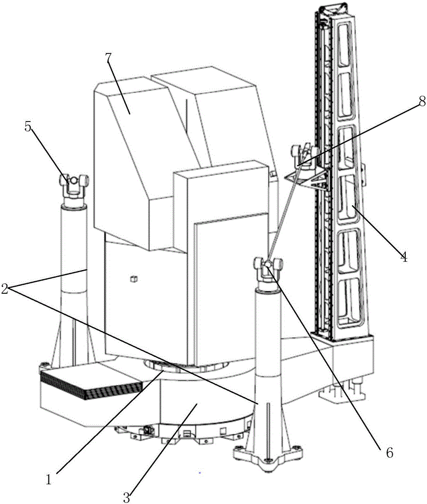
[0039] The spacecraft high-precision angle measurement system of the present invention includes a collimation measurement subsystem and a mechanical servo subsystem, wherein:

[0040] Such as figure 1 As shown, the mechanical servo subsystem includes a spacecraft parking frame 1, a reference positioning support 2, a circular turntable 3, a vertical movement support 4, and a spacecraft body 7. The alignment measurement subsystem includes a first reference theodolite 5, a second reference theodolite...


PUM


Abstract

The invention provides a high precision angle measurement system and method for a spacecraft. The high precision angle measurement system comprises an alignment measurement subsystem and a mechanical servo subsystem, wherein the mechanical servo subsystem comprises a spacecraft parking frame and the like; the alignment measurement subsystem comprises a first benchmark theodolite and the like; in a using process, a spacecraft body is statically put on the spacecraft parking frame; the first benchmark theodolite and a second benchmark theodolite are fixedly arranged on a benchmark locating support; an alignment theodolite is fixed on a vertical motion support and moves up and down along the vertical motion support; and the whole vertical motion support is mounted on an annular rotating table, the annular rotating table realizes rotation in the azimuth of 0-360 degrees, and motion of the whole mechanical servo system can form a cylindrical space at one height. The high precision angle measurement system provided by the invention adopts a CCD photoelectric auto-collimator for replacing the traditional optical theodolite telescope system, so that the accuracy and stability of measured data are improved, and the high precision angle measurement system has an automatic reading function.

Description

technical field [0001] The invention relates to a spacecraft measurement system and method, in particular to a spacecraft high-precision angle measurement system and method. Background technique [0002] In the process of spacecraft assembly, the coordinate system composed of any three adjacent reflective surfaces in the optical cube mirror (regular hexahedron) is usually used to represent the angular attitude of the equipment. The actual measurement of the attitude of the equipment is the normal between the reflective surfaces of the cube mirror. See angle. At present, it is widely used at home and abroad to use multiple electronic theodolites to build online measurement methods, such as Leica's TM5100A / TM6100A, etc., through multiple theodolites to collimate the cubic mirrors to be measured at the same time, and then aiming at each other according to needs. The mirror vector to be measured is transferred to the station coordinate system of the theodolite, and finally the ...

Claims


Application Information

Patent Timeline
Patent Type & Authority Applications(China)
IPC IPC(8): G01C1/02
CPCG01C1/02
Inventor 李强陈伟男汤红涛杨凯马海龙
Owner SHANGHAI INST OF SATELLITE EQUIP
Why Eureka
Try Eureka