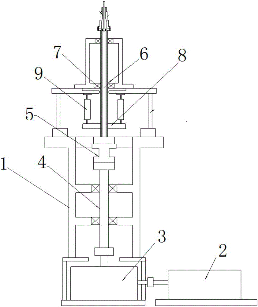
Tail rotor stand

A tail rotor and bench technology, applied in the field of the tail rotor table, can solve the problems of harsh working environment, the test capacity of the tail rotor test bench cannot meet the tail rotor, etc., and achieve the effects of improving the working environment, solving installation difficulties and accurate test data.

Active Publication Date: 2017-03-22
CHINA HELICOPTER RES & DEV INST
View PDF5 Cites 13 Cited by
  • Summary
  • Abstract
  • Description
  • Claims
  • Application Information

AI Technical Summary

Problems solved by technology

[0003] The test capability of the previous tail rotor test bench (not universal) could not meet the requirements of the high-power test of the tail rotor ground bench. At the same time, the horizontal installation of the tail rotor made the working enviro

Method used


Image

  • Tail rotor stand

Examples


Embodiment Construction

[0030] In order to make the objectives, technical solutions and advantages of the present invention clearer, the technical solutions in the embodiments of the present invention will be described in more detail below in conjunction with the drawings in the embodiments of the present invention. In the drawings, the same or similar reference numerals denote the same or similar elements or elements having the same or similar functions throughout. The described embodiments are some, but not all, embodiments of the invention. The embodiments described below by referring to the figures are exemplary and are intended to explain the present invention and should not be construed as limiting the present invention. Based on the embodiments of the present invention, all other embodiments obtained by persons of ordinary skill in the art without creative efforts fall within the protection scope of the present invention. Embodiments of the present invention will be described in detail below ...


PUM


Abstract

Disclosed in the invention is a tail rotor stand comprising a rack, a horizontal motor, a reducer, a first driving shaft assembly, a torque scale, a second driving shaft assembly, a single-component lift balance, a rotating translation conversion device, and an actuator cylinder set. The rack includes a support platform, a driving shaft support part, and an accommodation space. The reducer is arranged in the accommodation space and the input terminal of the reducer is connected with the output terminal of the horizontal motor. The first driving shaft assembly is arranged inside the driving shaft support part and can rotate relative to the driving shaft support part; and one end of the driving shaft assembly is connected with the output terminal of the reducer. The torque scale is connected with the other end of the first driving shaft assembly. One end of the second driving shaft assembly is in transmission connection with the torque scale and the other end is in transmission connection with a tail rotor. The single-component lift balance is arranged on the support platform; a floating plate of the single-component lift balance is connected with the second driving shaft assembly. The rotating translation conversion device is in transmission connection with the second driving shaft assembly. A cylinder body of the actuator cylinder set is arranged on the floating plate and a piston rod is connected with the rotating translation conversion device.

Description

technical field [0001] The invention relates to the technical field of tail rotor test, in particular to a tail rotor platform. Background technique [0002] Helicopter rotor system includes main rotor and tail rotor (except for twin rotors and some new helicopters), which affects the life, flight quality, safety, performance and full-cycle use cost of the helicopter, and determines the success or failure of the model development. The motion and structure of the rotor system are very complex, so the research on the dynamic characteristics and aerodynamics of helicopters is an endless topic in the helicopter industry. Although the finite element theory, computing technology, and computer hardware facilities are developing at a high speed, it is possible to study problems in fluid mechanics through models and calculations, but there is still a long way to go to truly reflect the characteristics of the rotor. In order to truly reflect the inherent characteristics, vibration le...

Claims


Application Information

Patent Timeline
IPC IPC(8): G01M13/00G01M9/00B64F5/60
CPCG01M9/00G01M13/00
Inventor 杨月赵云邵华松张文静
Owner CHINA HELICOPTER RES & DEV INST
Why Eureka
Try Eureka