Bypass operation low voltage rapid conversion device, and monitoring, releasing and displaying methods thereof

A fast switching, low-voltage technology, used in emergency protection circuit devices, indicating the existence of current/voltage, electrical components, etc., can solve the problems of unsafe, reliable and effective safety warning protection, many operating points involving a wide range, and heavy maintenance work. , to achieve the effect of fast and effective safety protection of live maintenance construction personnel, protection of life and property safety, and avoidance of accidents.

Inactive Publication Date: 2017-03-22
STATE GRID SHANDONG ELECTRIC POWER COMPANY WEIFANG POWER SUPPLY
View PDF5 Cites 2 Cited by
  • Summary
  • Abstract
  • Description
  • Claims
  • Application Information

AI Technical Summary

Problems solved by technology

[0003] The present invention is provided to solve the problems existing in the existing power grid live inspection and maintenance construction operations, such as many operating points on the construction site involving a wide range of areas, heavy maintenance work, safety warning protection that cannot be carried out safely, reliably and effectively, and large hidden dangers in maintenance and construction operations. A fast breaking, automatic and manual closing and opening, with voltage display, current display that is tracking protection and opening and closing status display, to a greater extent improve the safety and reliability of construction workers for live maintenance maintenance workers Low-voltage fast switching device for road work and methods for monitoring, tripping and displaying the same

Method used


Image

  • Bypass operation low voltage rapid conversion device, and monitoring, releasing and displaying methods thereof
  • Bypass operation low voltage rapid conversion device, and monitoring, releasing and displaying methods thereof
  • Bypass operation low voltage rapid conversion device, and monitoring, releasing and displaying methods thereof

Examples


Embodiment 1

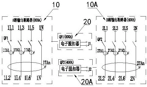
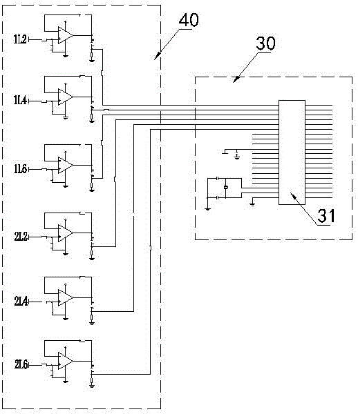
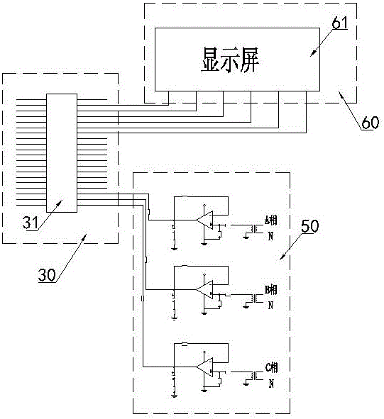
[0034] figure 1 , figure 2 , image 3 , Figure 4 , Figure 5 In the illustrated embodiment, a low-voltage rapid conversion device for bypass operation is built into a live working vehicle, and includes a voltage detection module 40, a current detection module 50, a zero sequence current detection module 70, a control module 30, a display module 30, and a circuit breaker. The circuit breaker is located on the side of the three-phase voltage outlet. The circuit breaker is individually controlled by the corresponding electronic release to disconnect. The voltage detection module collects the A, B, and C phase voltages at the outlet of the circuit breaker. The voltage transformer and operational amplifier are processed to output voltage detection signals; the current detection module collects the A, B, and C phase currents at the outlet end of the circuit breaker, and the current detection signals are output after processing by the current transformer and operational amplifier; the...

Embodiment 2

[0042] Image 6 In the illustrated embodiment, a detection method for low-voltage rapid conversion of bypass operation includes the following steps:

[0043] Collecting the A, B, and C phase voltages of Embodiment 1, respectively processing the A, B, and C phase voltages to obtain the phase voltage detection step 41 of the effective phase voltage display value;

[0044] According to the effective value of the phase A, B, and C voltages, the voltage is automatically connected or manually connected to the voltage in step 42;

[0045] Collect the A, B, and C phase currents respectively formed after the A, B, and C phase voltages of Example 1 are connected, and process the A, B, and C phase currents respectively to obtain the effective phase current amplitude display of Example 1. Value of phase current detection step 43;

[0046] Collect the zero sequence phase current formed after the A, B, and C phase voltages of embodiment 1 are connected, and process the zero sequence current to obta...

Embodiment 3

[0049] Figure 7 In the illustrated embodiment, a low-voltage rapid transfer trip method for bypass operation includes the following steps:

[0050] Rated current setting step 51 of setting multiple rated phase current reference values ​​and multiple rated zero sequence current reference values, each reference value represents the rated phase current or the rated zero sequence current of embodiment 1 of different multiples;

[0051] Set the disconnection time setting step 52 of the disconnection time corresponding to multiple rated phase current reference values ​​and multiple rated zero sequence current reference values; the disconnection time value follows the rated zero sequence current reference value or the rated zero sequence current The reference value increases and decreases;

[0052] The comparison result of the phase current detection signal obtained by the detection with the set reference value of the rated phase current is used to determine whether to control the trip ste...


PUM


Abstract

The invention discloses a bypass operation low voltage rapid conversion device, and monitoring, releasing and displaying methods thereof. A circuit breaker is individually disconnected by the electronic release control, and a voltage detection module collects ABC phase voltages of outlet ends of the circuit breaker and then outputs voltage detection signals. A current detection module collects ABC phase currents of the outlet ends and then outputs current detection signals. A zero sequence current detection module collects zero sequence currents of the outlet ends of the circuit breaker and then outputs zero sequence current detection signals. A control module is coupled to a display module, the voltage detection module, the current detection module and the zero sequence current detection module. The display module displays amplitudes of the ABC phase voltages and the ABC phase currents and amplitudes of the zero sequence currents. The control module determines the control of an electronic release to disconnect the circuit breaker according to the detected phase current amplitude or zero sequence current amplitude. The bypass operation low voltage rapid conversion device achieves quick disconnection, automatic and manual switching on and off, and multi-parameter state display, thereby improving the safety and reliability of construction operations of live-line maintenance operators for power grids.

Description

Technical field [0001] The invention relates to a high-voltage detection technology, in particular to a bypass operation low-voltage rapid conversion device used in the power grid live-line maintenance operation and a monitoring, tripping and display method thereof. Background technique [0002] With the rapid development of my country's power grid business, live maintenance has become an inevitable and important means to effectively ensure the safe operation of the power grid and stable power supply. At the same time, it also poses a severe challenge to the maintenance and repair workers in the live work, and a little carelessness will cause Life safety threats. In the course of the work, due to the cumbersome work procedures and harsh working environment, the operators tend to ignore the dangers around them, resulting in unintentionally getting too close to the high-voltage live equipment, resulting in casualties of the maintenance workers. Therefore, how to effectively guarant...

Claims


Application Information

Patent Timeline
Patent Type & Authority Applications(China)
IPC IPC(8): G01R19/145H02H11/00
CPCG01R19/145H02H11/00
Inventor 马献辉杨栋张金良于欣吴冰王路刘其博姚文展张凯李金宝孙华忠高希伟于金亮邵明波辛洪杰高兴琳尹磊毕盛伟辛庚鑫乔丕凡张兆慧段磊徐鹏刘五超王杰黄松林贾俊超
Owner STATE GRID SHANDONG ELECTRIC POWER COMPANY WEIFANG POWER SUPPLY
Why Eureka
Try Eureka