Method and system for adjusting optical uniformity of liquid crystal modules

An optical uniformity, liquid crystal module technology, applied in optics, nonlinear optics, instruments, etc., can solve the problems of light intensity difference of surface light source, poor optical uniformity of liquid crystal display, etc., and achieve the effect of improving optical uniformity

Active Publication Date: 2017-03-22
SHENZHEN TCL DIGITAL TECH CO LTD
View PDF5 Cites 5 Cited by
  • Summary
  • Abstract
  • Description
  • Claims
  • Application Information

AI Technical Summary

Problems solved by technology

In the prior art, the liquid crystal module is composed of an LED light source assembly, an optical film and a Liquid Crystal Display (LCD), and each LED light source passes through the optical film to form a surface light source corresponding to the pixel plane of the liquid crystal display. , due to the variance of the LED light source and the assembly error of the optical film, as well as the influence of many discrete factors such as the optical parameters of the LED light source (such as light intensity or light type), the position of the LED, and the light guide characteristics of the optical film, etc., resulting in There are differences in light intensity between surface light sources incident on different areas of the LCD surface
[0003] The disadvantage of the above technical solution is that the optical uniformity of the liquid crystal display is not good

Method used


Image

  • Method and system for adjusting optical uniformity of liquid crystal modules
  • Method and system for adjusting optical uniformity of liquid crystal modules
  • Method and system for adjusting optical uniformity of liquid crystal modules

Examples


Embodiment Construction

[0059] It should be understood that the specific embodiments described here are only used to explain the present invention, not to limit the present invention.

[0060] The invention provides a method for adjusting the optical uniformity of a liquid crystal module.

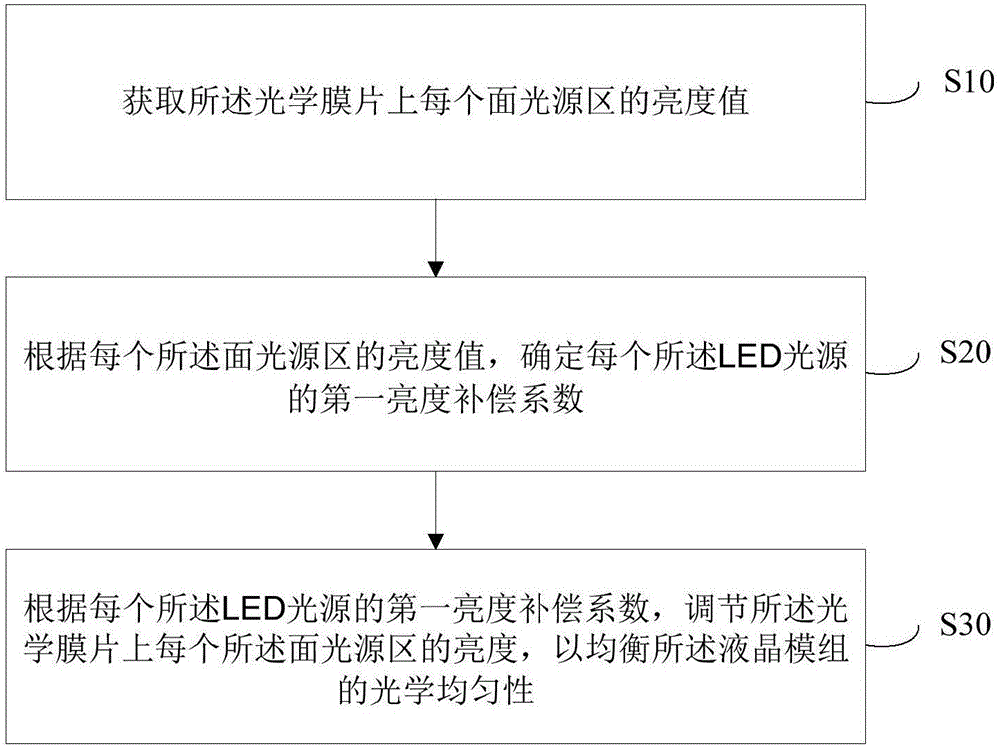
[0061] see figure 1 , in order to achieve the above object, the first embodiment of the present invention provides a method for adjusting the optical uniformity of a liquid crystal module, the liquid crystal module includes an LED light source matrix and an optical film arranged facing each other, and the optical film is arranged on the optical film The liquid crystal display on the side of the sheet away from the LED light source matrix, the side of the optical film away from the LED light source matrix is ​​the light output side, and the method for adjusting the optical uniformity of the liquid crystal module includes the following steps:

[0062] Step S10, acquiring the luminance value of each surface light so...


PUM


Abstract

The invention discloses a method for adjusting the optical uniformity of liquid crystal modules. The liquid crystal modules comprise LED light source matrixes, optical films and liquid crystal display screens. The LED light source matrixes face the optical films; each liquid crystal display screen is arranged on the side, which is deviated from the corresponding LED light source matrix, of the corresponding optical film; and a light emergent side is arranged on the side, which is deviated from the corresponding LED light source matrix, of each optical film. The method for adjusting the optical uniformity of the liquid crystal modules includes steps of acquiring brightness values of each surface light source region of each optical film; determining first brightness compensation coefficients of each LED light source according to the brightness values of the corresponding surface light source region; adjusting the brightness of each surface light source region on the corresponding optical film according to the first brightness compensation coefficients of the corresponding LED light source so as to balance the optical uniformity of the liquid crystal modules. The invention further provides a system for adjusting the optical uniformity of the liquid crystal modules. According to the technical scheme, the method and the system have effect of improving optical uniformity of liquid crystal display screens.

Description

technical field [0001] The invention relates to the technical field of liquid crystal modules, in particular to a liquid crystal module optical uniformity adjustment method and a liquid crystal module optical uniformity adjustment system. Background technique [0002] The LCD module is the display part of the LCD TV. In the prior art, the liquid crystal module is composed of an LED light source assembly, an optical diaphragm and a Liquid Crystal Display (LCD), and each LED light source passes through the optical diaphragm to form a surface light source corresponding to the pixel plane of the liquid crystal display. , due to the difference of the LED light source and the assembly error of the optical film, as well as the influence of many discrete factors such as the optical parameters of the LED light source (such as light intensity or light type), the position of the LED, and the light guide characteristics of the optical film, etc., resulting in There are differences in l...

Claims


Application Information

Patent Timeline
Patent Type & Authority Applications(China)
IPC IPC(8): G02F1/13357
CPCG02F1/133603G02F1/133606G02F1/133611G02F1/133607
Inventor 任兴业严方红刘建军
Owner SHENZHEN TCL DIGITAL TECH CO LTD
Why Eureka
Try Eureka