Autonomous precision landing system of unmanned aerial vehicle on motion platform and landing method

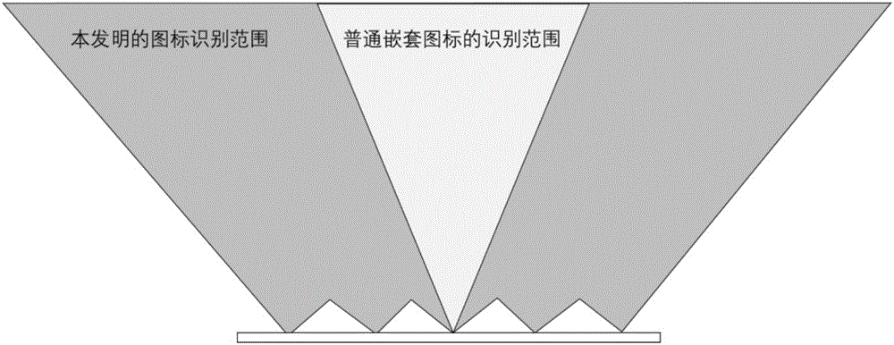
A motion platform and landing system technology, applied in the field of unmanned aerial vehicles, can solve problems such as inability to calculate accurate position information, unstable vehicle speed, and misrecognition as icons, etc., to increase the recognizable range, increase the recognition angle, and ensure accuracy. Effect

Inactive Publication Date: 2017-03-22
BEIJING INSTITUTE OF TECHNOLOGYGY
View PDF7 Cites 38 Cited by
  • Summary
  • Abstract
  • Description
  • Claims
  • Application Information

AI Technical Summary

Problems solved by technology

Because they are exactly the same, the computer cannot judge whether it recognizes a large icon or a small icon during recognition, so it cannot calculate the accurate position information, and can only get the pixel deviation between the icon and the center of the screen (for example, the x-axis is offset by 100 pixels, and the y-axis is offset by 100 pixels. 150 pixels), which greatly reduces the control accuracy of the UAV. Generally, it is only suitable for landing on a stationary platform. On a moving platform, pixel deviation alone cannot meet the requirements of precise landing.
In the landing experiment of the moving platform, the concentrically nested icons also exposed a serious problem: the recognizable range of the icon is a cone that gradually expands upwards with the center of the icon as the apex, such as image 3 As shown in , the lower the flight altitude (or the smaller the distance between the camera and the icon), the smaller the recognizable range in the horizontal direction
The vehicle speed is unstable when the moving platform lands. When the drone descends to a very low position, once the vehicle speed changes, the drone is easy to leave the recognizable range, resulting in landing failure
[0006] 2. Existing image recognition algorithms cannot handle icons captured by tilted cameras
Most of the icons used in existing visual positioning are based on shapes, such as rectangles, circles, and triangles. The recognition method of such icons is to analyze the outline of the icon. If the outline is consistent with the preset shape, the recognition is considered successful. If the camera Slanted, due to the perspective effect, the captured icon is no longer a standard shape, so it cannot be recognized
Therefore, even if the gimbal is added, it cannot be recognized and positioned normally when the shooting angle is large, and the gimbal cannot be used to expand the recognition range
[0007] 3. The existing icons are too simple in shape and judged only by the outline of the shape, without considering the recognition of the entire surface of the icon, the judgment conditions are not rigorous enough, and it is easy to misidentify other objects on the ground as icons
[0008] 4. The existing vision-assisted landing mostly uses a vertically downward camera fixedly connected to the rotor UAV. This method has a small field of view and is affected by the attitude of the rotor UAV.
When the drone is flying fast, the camera is always in a tilted state, so that the icon cannot enter the camera's field of view

Method used


Image

  • Autonomous precision landing system of unmanned aerial vehicle on motion platform and landing method
  • Autonomous precision landing system of unmanned aerial vehicle on motion platform and landing method
  • Autonomous precision landing system of unmanned aerial vehicle on motion platform and landing method

Examples


Embodiment Construction

[0051] The present invention will be described in detail below in conjunction with the accompanying drawings and embodiments.

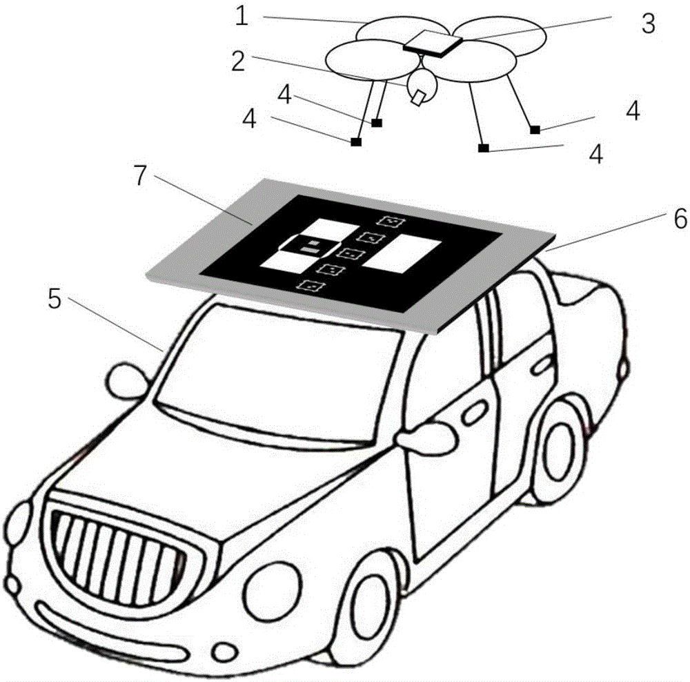
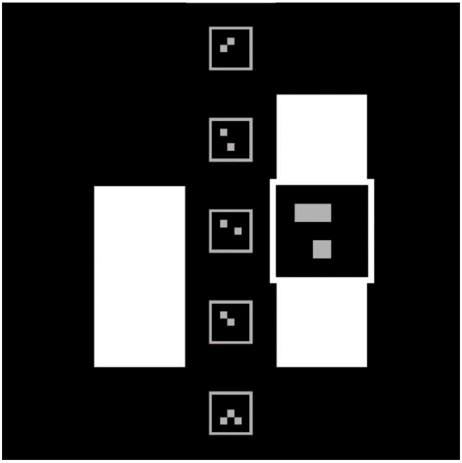
[0052] The present invention designs a specially designed multi-layer nested two-dimensional code identification, and uses the existing pan-tilt camera of the rotor UAV to provide a vision-assisted autonomous landing of the rotor UAV with high precision, good reliability and low cost system, especially for landing on top of moving vehicles. Its system consists of figure 1 As shown, it includes a rotor UAV 1, an airborne pan-tilt camera 2, an on-board computer 3, an airborne landing gear magnetic device 4, a vehicle-mounted iron landing pad 6, and a multi-layer nested logo 7;

[0053] The rotor UAV 1 refers to a complete UAV system, including a UAV, a remote controller (or a ground station), and the UAV consists of a frame, a propeller motor, an electric regulator, a sensor, and a flight controller; wherein Sensors include accelerometer, gyroscope, ...


PUM


Abstract

The invention provides an autonomous precision landing system of an unmanned aerial vehicle on a motion platform and a landing method. The autonomous precision landing system comprises a rotor unmanned aerial vehicle 1, an airborne platform camera 2, an airborne computer 3, airborne undercarriage magnetic devices 4, a vehicle-mounted iron ground 6 and a multi-layer nested identifier 7, wherein the multi-layer nested identifier 7 is composed of two-dimensional codes which are mutually overlapped, different in size, different in pattern and asymmetric in distribution; the two-dimensional codes with a small size cover the two-dimensional code with a large size; the two-dimensional code with a large size is covered with a plurality of two-dimensional codes with a small size along the advancing direction of a motor vehicle 5, and the number of the two-dimensional code with the maximum size is only one. According to the invention, the platform camera carried by the rotor unmanned aerial vehicle is utilized, the multi-layer nested identifier 7 is recognized by adopting the airborne platform camera 2, a vision-assisted rotor unmanned aerial vehicle autonomous landing system which is high in precision, good in reliability and low in cost is provided, and the system is particularly applicable to landing at the top end of a moving motor vehicle.

Description

technical field [0001] The invention belongs to the technical field of unmanned aerial vehicles, and in particular relates to an autonomous and precise landing system and landing method for unmanned aerial vehicles on a moving platform. Background technique [0002] Nowadays, small rotor UAVs are more and more widely used in various military and civilian industries, such as plant protection, power inspection, aerial photography, and post-disaster rescue. The usual method of use is to use a car to carry the rotor UAV to the mission area. Control the rotor drone to take off, perform missions, and finally land on the ground. A large open space is usually required when landing. Due to the poor positioning accuracy of the rotor UAV, it takes a long time to land, the control effect is poor, and accidents are prone to occur. If the rotor drone can be autonomously and accurately landed on the roof of the vehicle, it will save a lot of time and reduce the requirements for the landin...

Claims


Application Information

Patent Timeline
Patent Type & Authority Applications(China)
IPC IPC(8): G05D1/10G06K9/00G06K19/06
CPCG05D1/101G06K19/06056G06V20/13
Inventor 佘浩平王章龙司维永韦浪张本科
Owner BEIJING INSTITUTE OF TECHNOLOGYGY
Why Eureka
Try Eureka