Eureka AIR delivers breakthrough ideas for toughest innovation challenges, trusted by R&D personnel around the world.

Coupling Design Method of Star Gear Tooth Angle and Screw Groove Bottom Angle

A design method and technology of star gear teeth, applied in the direction of calculation, instrument, geometric CAD, etc., to achieve the effect of meeting the sealing requirements

Active Publication Date: 2019-04-12
XI AN JIAOTONG UNIV
View PDF2 Cites 0 Cited by
  • Summary
  • Abstract
  • Description
  • Claims
  • Application Information

AI Technical Summary

Problems solved by technology

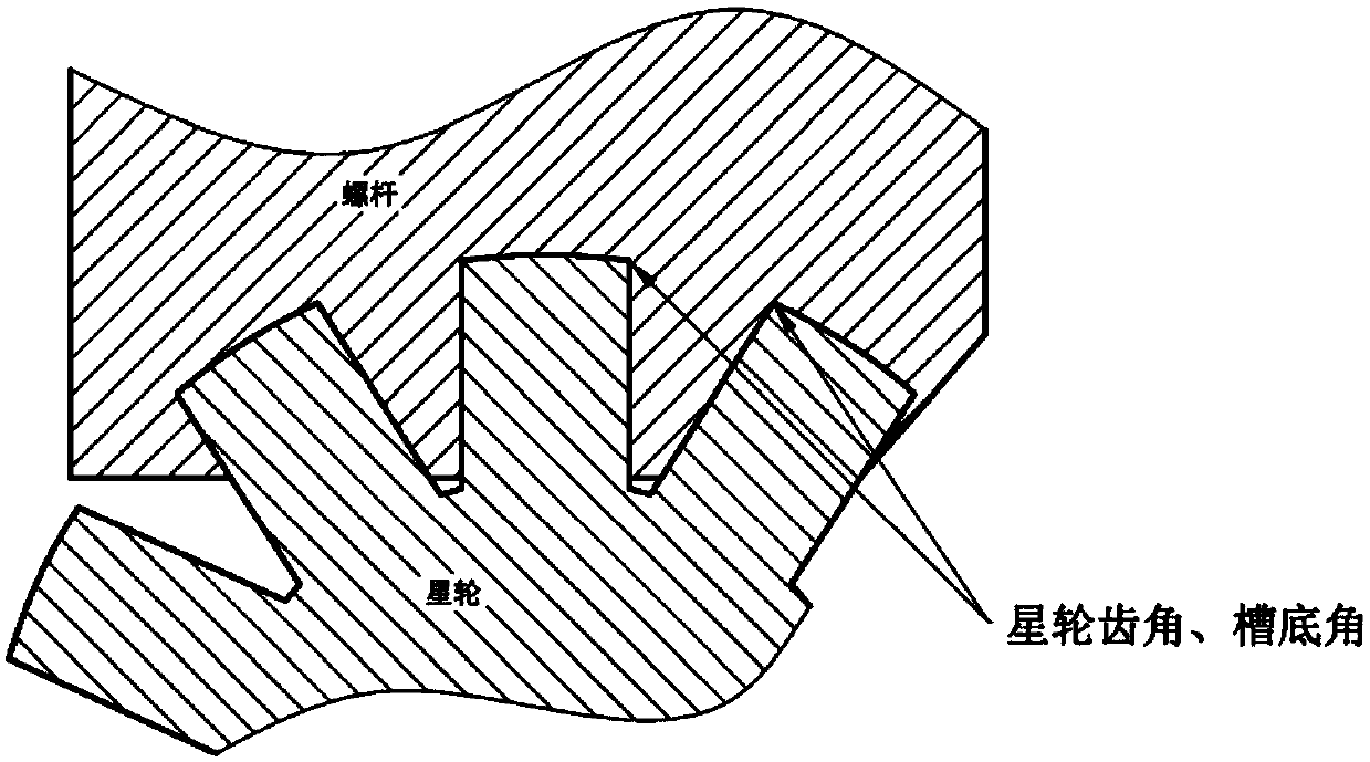
[0005] The purpose of the present invention is to provide a coupling design method for the tooth angle of the star wheel and the bottom angle of the screw groove, so as to solve the problems faced by the numerical control milling process of the meshing pair of the star wheel and the screw

Method used


Image

  • Coupling Design Method of Star Gear Tooth Angle and Screw Groove Bottom Angle
  • Coupling Design Method of Star Gear Tooth Angle and Screw Groove Bottom Angle
  • Coupling Design Method of Star Gear Tooth Angle and Screw Groove Bottom Angle

Examples


Embodiment 1

[0043] A coupling design method for a star gear tooth angle and a screw groove bottom angle profile, comprising the following steps:

[0044] 1) According to the principle of selecting a value greater than the radius of the ball head of the milling cutter as the radius of the enveloping arc, the transition arc of the alveolar bottom angle is formed.

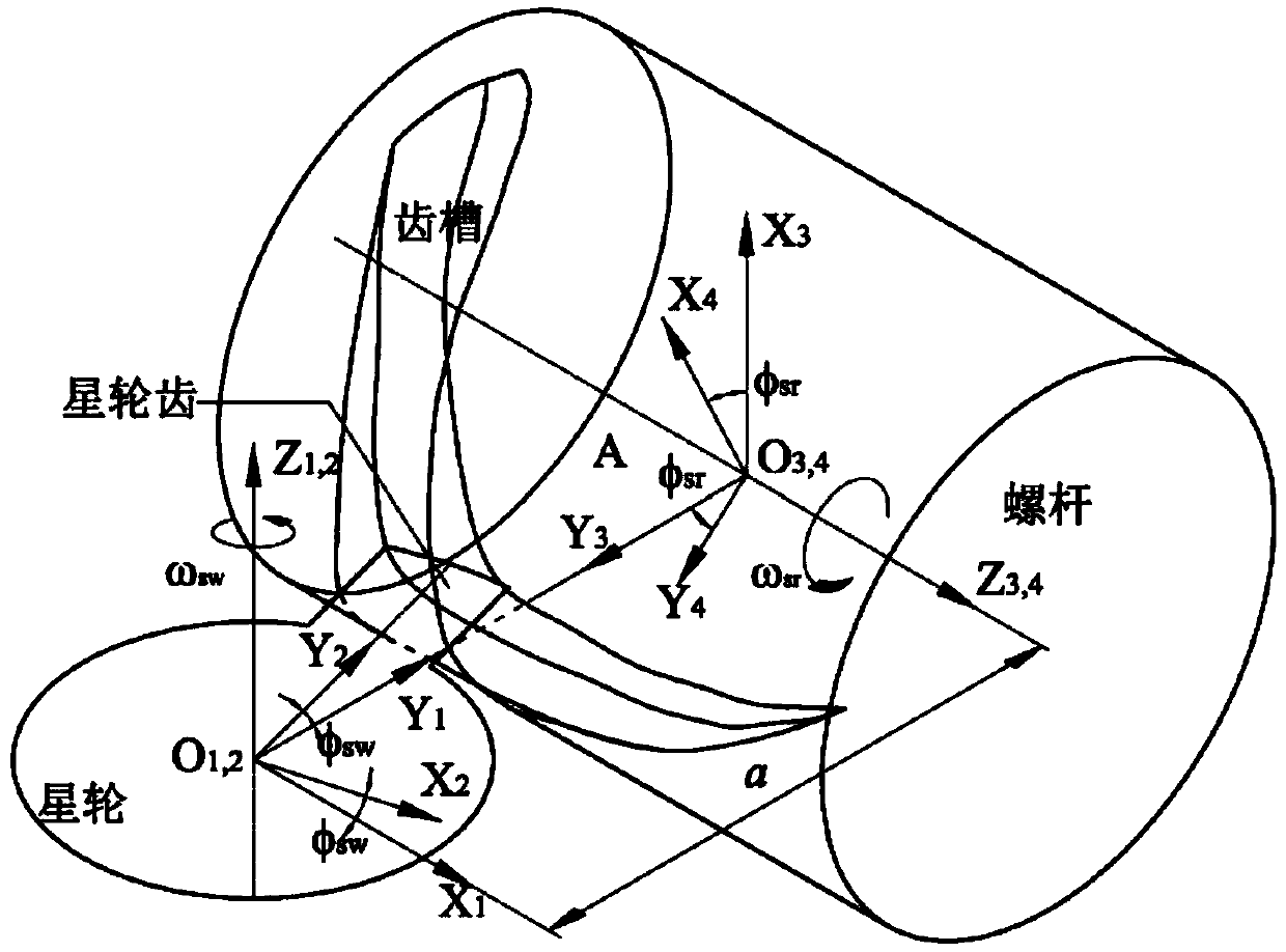
[0045] The motion relationship between the star wheel and the screw is as follows: figure 2 As shown, establish a comprehensive coordinate system: S1, S2, S3, S4. The fixed coordinate system S1 and S3 represent the initial positions of the star wheel teeth and the screw tooth groove respectively, Z1 coincides with the star wheel axis, Z3 coincides with the screw axis, O 1 o 3 It is the mid-perpendicular line of the two axes; the starting position of the moving coordinate system S2 is the same as that of S1, fixed on the star wheel; the starting position of the moving coordinate system S4 is the same as that of S3, fixed on the...

Embodiment 2

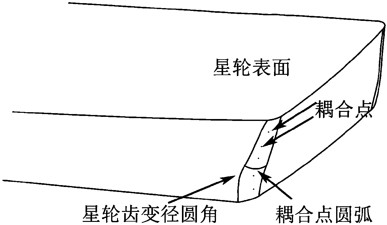
[0063] The method provided in this embodiment is to use a circular arc transition at the joint between the bottom surface and the side surface of the screw tooth groove (called the groove bottom angle), and use a corresponding variable-diameter ellipse circular arc transition for the tooth angle of the star wheel.

[0064] A coupling design method for a star gear tooth angle and a screw groove bottom angle profile, comprising the following steps:

[0065] 1) According to the principle of selecting a value greater than the radius of the ball head of the milling cutter as the radius of the enveloping arc, the transition arc of the alveolar bottom angle is formed.

[0066] The motion relationship between the star wheel and the screw is as follows: figure 2 As shown, establish a comprehensive coordinate system: S1, S2, S3, S4. The fixed coordinate system S1 and S3 represent the initial positions of the star wheel teeth and the screw tooth groove respectively, Z1 coincides with t...


PUM


Abstract

The invention discloses a profile coupling design method for a tooth angle of a star wheel and a groove bottom angle of a screw rod. The method comprises the steps of 1) forming a transitional circular arc of a bottom angle of a tooth groove according to a principle of selecting a value greater than the radius of a ball end of a milling cutter as the radius of an enveloping circular arc; and 2) forming a variable-diameter round angle of a tooth of a star wheel with the variable-diameter round angle at the tooth angle of the star wheel. According to the method, the joint (called the groove bottom angle) between the bottom surface and the side surface of the tooth groove of the screw rod adopts circular arc transition, and the tooth angle of the star wheel adopts corresponding circular arc or elliptic arc transition; and the tooth groove of the screw rod, designed with the method, is convenient for machining of a numerical control milling machine, and can ensure a design gap between the tooth angle of the star wheel and the groove bottom angle of the screw rod, and meet a seal requirement of a compressor / expander in a working process.

Description

technical field [0001] The invention belongs to the field of mechanical design, processing and manufacturing, and relates to a coupling design method for a star gear tooth angle and a screw groove bottom angle profile in a single screw compressor / expander. Background technique [0002] Single-screw compressor / expander has technical advantages such as ideal force balance, large unit capacity, small vibration, and low noise. It is widely used in various fields such as chemical industry, steel, refrigeration, and aerodynamics. [0003] The single-screw compressor / expander mainly relies on the precise meshing between the screw and the star wheel to realize its working process. The meshing pair is the heart of the single-screw compressor / expander. The machining accuracy and profile design of the meshing pair directly affect the machine. performance. With the application of new lines such as cylindrical envelope, multi-cylindrical envelope and curved line, the processing of singl...

Claims


Application Information

Patent Timeline
Patent Type & Authority Patents(China)
IPC IPC(8): G06F17/50
CPCG06F30/17
Inventor 吴伟烽张曌建志方杨良伟侯方勇
Owner XI AN JIAOTONG UNIV
Why Eureka
Eureka Blog
Learn More