Biological recognition device and biological recognition method

A technology of biometric identification and acquisition unit, applied in the field of biometric identification, can solve the problems that the detection value is not the real distance value, the sensor receives the wrong signal, etc., and achieve the effect of enhancing security, wide application range and high precision

Inactive Publication Date: 2017-03-22
BOE TECH GRP CO LTD +1
View PDF6 Cites 5 Cited by
  • Summary
  • Abstract
  • Description
  • Claims
  • Application Information

AI Technical Summary

Problems solved by technology

The sound wave is received by the sensor after multiple bounces, so the actual detection value is not the real distance value
3. Noise, although the operating frequency of most ultrasonic sensors is 40-45Khz, which is much higher than the frequency that humans can hear, but the surrounding environment will also produce noise of similar frequency, which will cause the sensor to receive wrong signals

Method used


Image

  • Biological recognition device and biological recognition method
  • Biological recognition device and biological recognition method
  • Biological recognition device and biological recognition method

Examples


Embodiment 1

[0030] An embodiment of the present invention provides a biometric identification device, which includes a plurality of micro-acquisition units and a processing unit 1 arranged in a preset array: wherein:

[0031] Each micro-acquisition unit is used to collect first signals corresponding to troughs and sweat pores on the fingerprint, and second signals corresponding to ridges, and convert the first and second signals into electrical signals and send them to the processing unit.

[0032] The processing unit is used for identifying at least one of troughs, ridges and sweat pores on the fingerprint according to the electrical signals sent by the multiple micro-acquisition units.

[0033] The specific size of each micro-acquisition unit can be set according to needs, so as to ensure that it can identify troughs, ridges and sweat pores.

[0034] Specifically, the processing unit includes an integrated circuit layer.

[0035] The working principle of the processing unit to identify...

Embodiment 2

[0041] The biometric identification device provided in this embodiment is similar to the biometric identification device provided in Embodiment 1 above, and the similarities between the two will not be repeated here, and only the differences between the two will be described below.

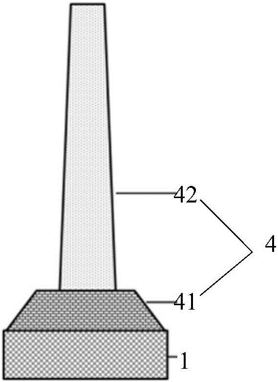
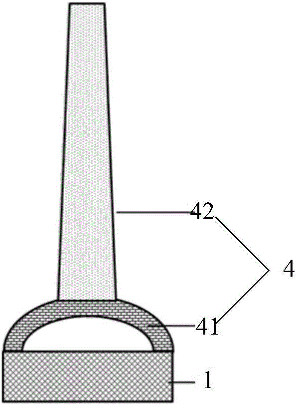
[0042] specifically, figure 1 and figure 2 It is a schematic structural diagram of two biometric identification devices provided in this embodiment. In this embodiment, the micro-acquisition unit 4 includes a piezoelectric material layer 41; wherein the piezoelectric material layer 41 is used to collect pressure signals corresponding to valleys, ridges and sweat pores on the fingerprint and convert them into electrical signals.

[0043] Specifically, since the troughs and sweat pores are concave relative to the ridges, when the fingerprint touches the micro-collection unit 4, the pressure signal sensed by the corresponding micro-collection unit 4 at the position of the troughs and sweat pores is...

Embodiment 3

[0055] The biometric identification device provided in this embodiment is similar to the biometric identification devices provided in the above-mentioned embodiments 1 and 2, and the similarities between the two will not be repeated here, and only the differences between the two will be described below.

[0056] specifically, Figure 5 is a schematic structural diagram of the biometric identification device in this embodiment. In this example, if Figure 5 As shown, the micro-acquisition unit 4 includes a capacitance formed by two electrodes 5, and senses signals through capacitance changes. Specifically, since the troughs and sweat pores are concave relative to the ridges, when a fingerprint touches a plurality of micro-collection units 4, the corresponding micro-collection units 4 at the positions of the troughs and sweat pores cannot be in contact with the finger. Therefore, If the capacitance does not change, the electrical signal brought by the capacitance change is 0, ...


PUM


Abstract

The invention provides a biological recognition device and a biological recognition method, and belongs to the field of biological recognition. The biological recognition device comprises a plurality of micro-acquisition units arranged according to a preset array, wherein each micro-acquisition unit is used for collecting a first signal corresponding to fingerprint troughs and sweat pores and a second signal corresponding to fingerprint ridges, converting the first signal and the second signal into electrical signals and sending the electrical signals to a processing unit; and the processing unit, which is used for identifying at least one of trough, ridge and sweat pore of a fingerprint according to the electrical signals sent by the plurality of micro-acquisition units. The size of each micro-acquisition unit is smaller with respect to the size of a conventional electrical square array, so that the number of minutia points extracted from collected images is relatively large, and biological recognition precision is high; the sweat pores can be recognized, and biological recognition can be realized through only dozens of sweat pores, and biological recognition can be carried out accurately under the condition of sweats and water; and through combination of sweat pore identification and trough and ridge identification, biological recognition safety, accuracy and uneasy replicability can be enhanced.

Description

technical field [0001] The invention belongs to the technical field of biological identification, and in particular relates to a biological identification device and a biological identification method. Background technique [0002] At present, biometric technology is more and more widely used in various fields. Due to the lifelong invariance, uniqueness and convenience of fingerprints, fingerprint recognition has almost become synonymous with biometrics. [0003] Current fingerprint identification methods mainly include contact (electrical) and non-contact (optical, ultrasonic). Among them, the non-contact type mainly uses light waves or ultrasonic sensors to transmit and receive waveforms reflected by finger troughs and ridges. Generally speaking, the effect of contact-type electrical fingerprint recognition is worse than that of non-contact optical or ultrasonic, because the contact area when the electrical sensor collects the image is much smaller than the area when the...

Claims


Application Information

Patent Timeline
IPC IPC(8): G06K9/00
CPCG06V40/1359G06V40/1306
Inventor 徐元杰臧鹏程刘庭良王杨
Owner BOE TECH GRP CO LTD
Why Eureka
Try Eureka