Visual course identification method based on target point identification

A recognition method and target point technology, applied in character and pattern recognition, image data processing, instruments, etc., can solve problems such as increased cost and inability to guarantee system reliability, and achieve improved accuracy, simple static calibration, and accurate positioning. Effect

Inactive Publication Date: 2017-03-22
BEIHANG UNIV
View PDF3 Cites 17 Cited by
  • Summary
  • Abstract
  • Description
  • Claims
  • Application Information

AI Technical Summary

Problems solved by technology

Although the use of high-performance inertial components and processors can guarantee high reliability, the cost will increase greatly; the use of low-performance inertial components or low-cost visual sensors alone can reduce costs, but cannot guarantee system reliability

Method used


Image

  • Visual course identification method based on target point identification
  • Visual course identification method based on target point identification
  • Visual course identification method based on target point identification

Examples


Embodiment

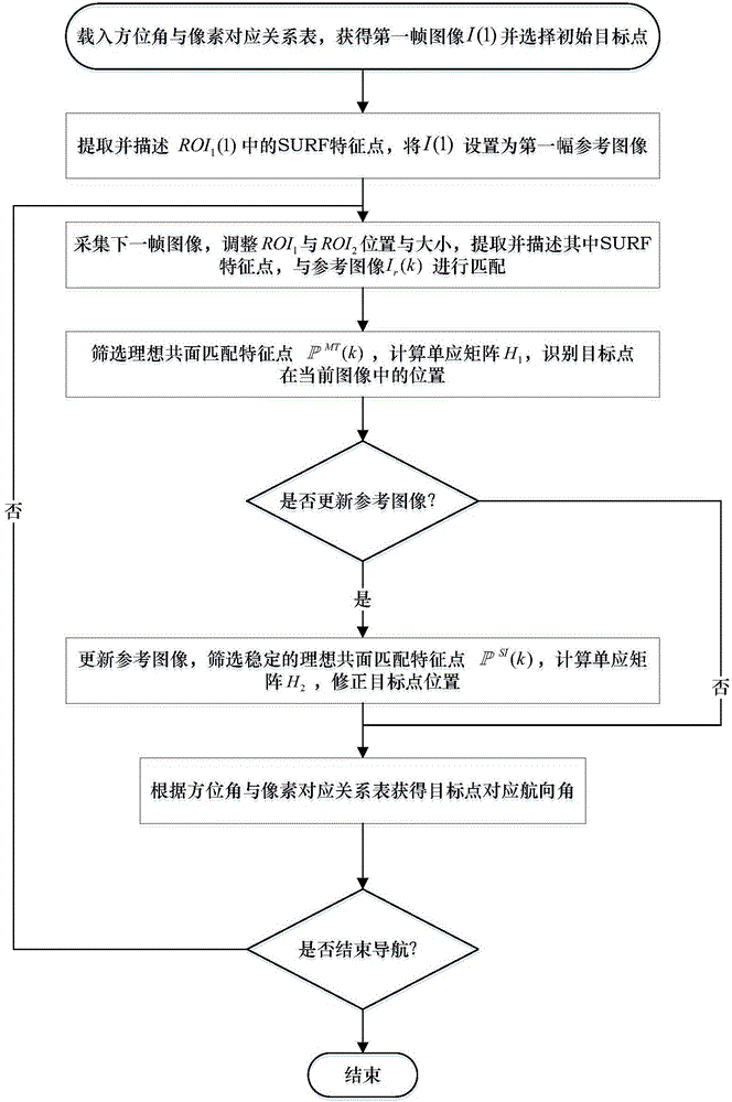
[0087] The invention is a visual heading calculation method based on target point recognition. The method proposes a feature-based target point recognition algorithm, and the visual heading can be accurately and effectively calculated according to the algorithm and camera calibration results. The implementation process of the method is as follows figure 1 As shown, the specific steps are as follows:

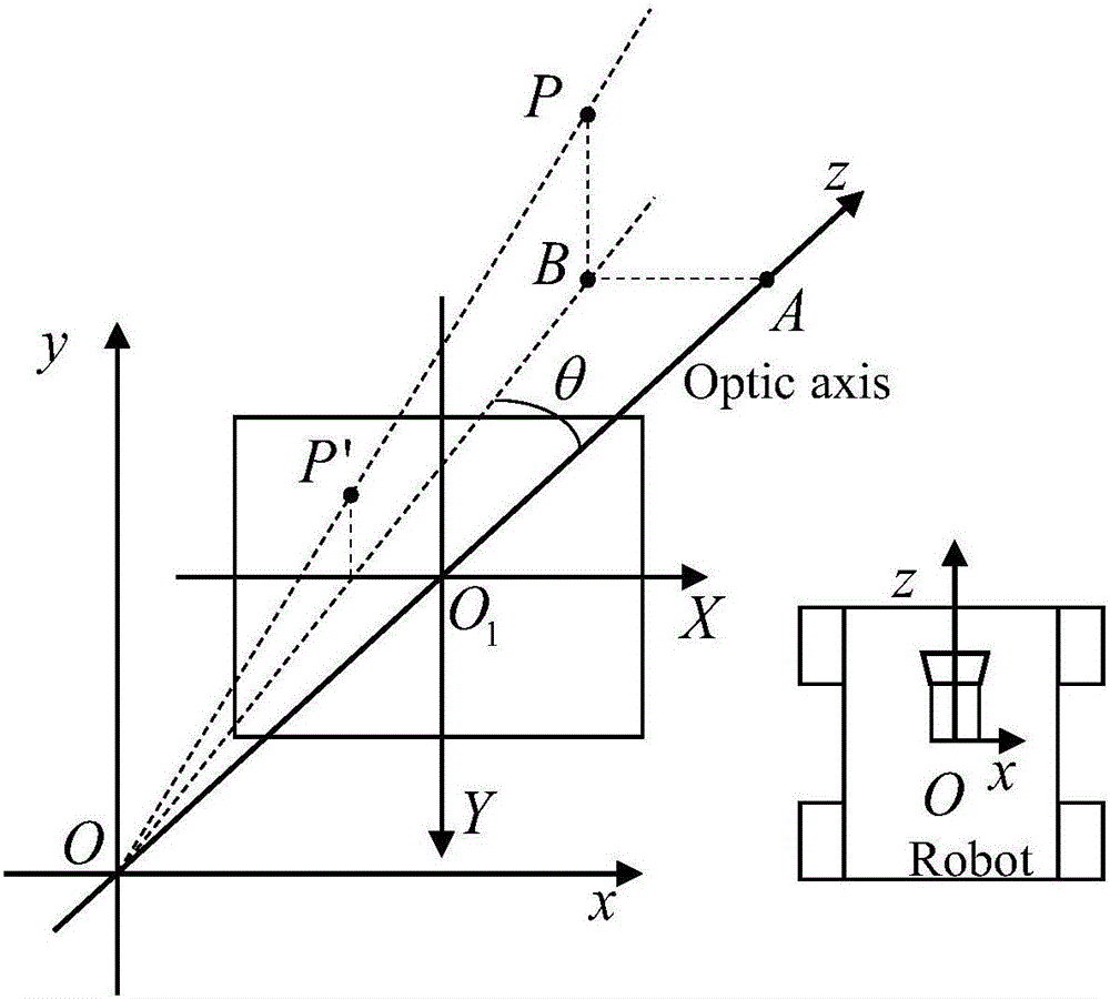
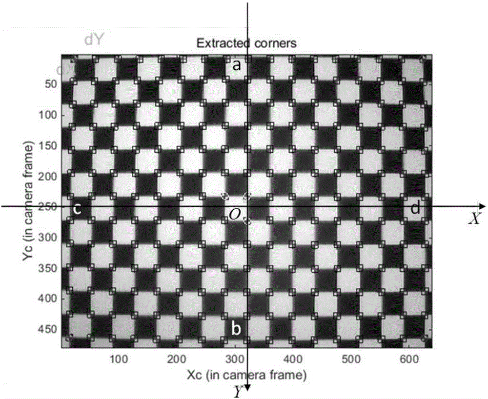
[0088] Step 1: According to such as figure 2 The imaging principle of the linear camera is shown, and the simple static calibration of the low-cost linear camera is carried out by using the checkerboard, and the corresponding relationship between the azimuth and the pixel is obtained, as shown in image 3 Shown is an image of a checkerboard target in the field of view;

[0089] Step 2: Load the azimuth-pixel correspondence table, obtain the first frame image I(1), and select the initial target point in I(1), such as Figure 5 As shown in (a), extract and describe the ROI 1 T...


PUM


Abstract

The invention discloses a visual course identification method based on a target point identification. The method comprises a step of loading an azimuth angle and pixel correspondence table obtained through camera calibration, selecting an initial target point in a first frame image, extracting and describing SURF characteristic points in first and second interest regions, and storing the frame image as a first reference image, a step of adjusting the position and size of an interest region in a collected next frame image, carrying out characteristic matching with the reference image, screen an ideal coplanar characteristic point, calculating a homography matrix, and identifying the current position of the target point, a step of updating the current frame image as the reference image when a reference image updating condition is satisfied, screening a stable ideal coplanar feature points set which is in accordance with affine transformation and is in a infinite plane, and correcting homography matrix and target point positions, and a step of finally identifying a target point corresponding course according to the azimuth angle and pixel correspondence table.

Description

technical field [0001] The invention relates to a visual heading recognition method based on target point recognition, and belongs to the technical field of visual / inertial combined navigation. Background technique [0002] The navigation system plays an important role in the complex motion of autonomous mobile robots. The integrated navigation system, which is composed of basic navigation technologies such as vision, inertia, GPS and GPS-like systems, ranging and direction recognition, has been extensively researched and developed. [0003] Visual navigation and inertial navigation are typical independent navigation systems. They can provide reliable navigation services without the help of external conditions, especially when GPS is unavailable and other complicated situations. The instant localization and mapping (SLAM) algorithm is currently the most commonly used algorithm for localization and navigation of autonomous mobile robots. Based on a large number of matchable...

Claims


Application Information

Patent Timeline
Patent Type & Authority Applications(China)
IPC IPC(8): G06K9/62G06T3/00G06T7/00
CPCG06T3/0075G06V10/751
Inventor 张海崔显光郭雷张晓鸥
Owner BEIHANG UNIV
Why Eureka
Try Eureka