Power cabin

A power cabin and hatch cover technology, applied in the field of power cabins, can solve the problems of being vulnerable to environmental interference and external impact, reducing the reliability of power systems, etc.

Active Publication Date: 2017-03-22
WUHAN TROOWIN POWER SYST TECH
View PDF17 Cites 0 Cited by
  • Summary
  • Abstract
  • Description
  • Claims
  • Application Information

AI Technical Summary

Problems solved by technology

[0005] At present, the electric stack and gas cylinder are installed in an external way, the gas cylinder is installed above the carrier, and the electric stack is installed below. The lines and hydrogen pipes on the electric stack are exposed to the outside, which is easily affected by environmental interference and external impact, which reduces the reliability of the entire power system. sex

Method used


Image

  • Power cabin
  • Power cabin
  • Power cabin

Examples


Embodiment Construction

[0047] The present invention will be further described in detail below in conjunction with the accompanying drawings, so that those skilled in the art can implement it with reference to the description.

[0048] In the description of the present invention, the terms "transverse", "longitudinal", "upper", "lower", "front", "rear", "left", "right", "vertical", "horizontal", " The orientations or positional relationships indicated by "top", "bottom", "inner", "outer", etc. are based on the orientations or positional relationships shown in the drawings, and are only for the convenience of describing the present invention and simplifying the description, and are not indicative or implied. It should not be construed as limiting the invention that a device or element must have a particular orientation, be constructed, and operate in a particular orientation.

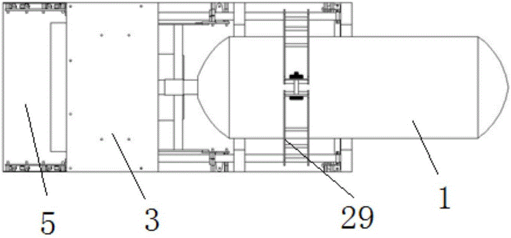
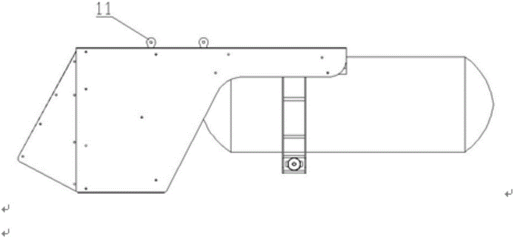
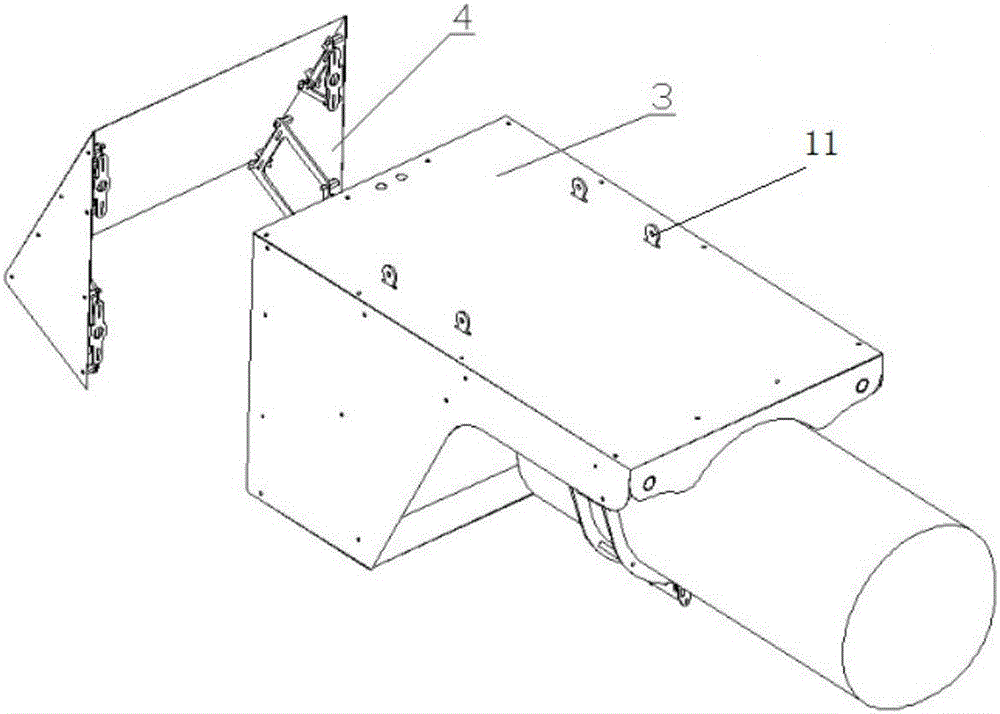
[0049] like Figure 1-11 As shown, the present invention provides a power cabin, including a cabin body, a hatch cover and a...


PUM


Abstract

The invention discloses a power cabin. The power cabin comprises a cabin body, a cabin cover and a fixed piece, wherein the cabin body comprises a frame structure and a cabin body skin, an accommodating space is arranged in the frame structure, the cabin body skin covers and is fixed on a top surface and a side surface of the frame structure, the fixed piece comprises a gas cylinder locking piece and an electric stack installation plate, the gas cylinder locking piece is arranged on a pair of first tube bodies in a penetrating way and is close to second ends of the first tube bodies, the electric stack installation plate is fixed on the pair of the first tube bodies and a pair of second tube bodies, the cabin cover comprises a cabin cover skin, and the cabin cover skin is arranged at one side, where a partition frame is arranged, of the frame structure and is in seamless transition with a joint part of the cabin body skin. In the power cabin, an electric stack and a gas cylinder module are integrated, the electric stack and a gas cylinder main part are sealed in the power cabin, water and dust prevention on the electric stack is achieved, and the reliability of the whole power system is improved; and the power cabin is installed by employing a fixed rack mode and can be arranged on a carrier by a screw.

Description

technical field [0001] The invention relates to the field of fuel cells. More specifically, the invention relates to a power pod. Background technique [0002] The pod refers to a streamlined nacelle section that is installed with certain airborne equipment or weapons and is hung under the fuselage or wing. It can be fixed or detachable, such as engine pods, weapon pods, etc. The addition of pods can make the aircraft have functions that it does not have. The addition of pods usually requires the support of onboard electronic equipment and consideration of the overall aerodynamics of the aircraft. [0003] With the development of aviation technology, airborne pod technology has also made great progress. Generally speaking, airborne pods can be divided into: weapon pods (including aircraft gun pods, aviation rocket pods), reconnaissance pods, fire control pods, and logistics auxiliary pods (refueling pods). [0004] The fuel cell power system has the characteristics of hi...

Claims


Application Information

Patent Timeline
Patent Type & Authority Applications(China)
IPC IPC(8): H01M2/10B64D29/00B64C7/02H01M50/20
CPCB64C7/02B64D29/00H01M50/20Y02E60/10
Inventor 陈伟张榕李骁
Owner WUHAN TROOWIN POWER SYST TECH
Why Eureka
Try Eureka