Rapid heating battery

A technology for heating electrodes and heating circuits, which is applied in secondary batteries, battery temperature control, circuits, etc. It can solve the problems that the application of AC or DC current to the battery cells cannot predict the impact on battery performance and life, and the heating efficiency is low. Excellent heating effect

Pending Publication Date: 2017-03-22
XIAMEN HUARONG ENERGY TECH
View PDF17 Cites 14 Cited by
  • Summary
  • Abstract
  • Description
  • Claims
  • Application Information

AI Technical Summary

Problems solved by technology

The above two heating methods, the existing heating methods have disadvantages, the external heating efficiency is low, a

Method used


Image

  • Rapid heating battery
  • Rapid heating battery
  • Rapid heating battery

Examples


Embodiment Construction

[0016] Embodiments of the present invention are described in detail below, examples of which are shown in the drawings, wherein the same or similar reference numerals designate the same or similar elements or elements having the same or similar functions throughout. The embodiments described below by referring to the figures are exemplary only for explaining the present invention and should not be construed as limiting the present invention.

[0017] In describing the present invention, it should be understood that the terms "center", "longitudinal", "transverse", "upper", "lower", "front", "rear", "left", "right", " The orientations or positional relationships indicated by "vertical", "horizontal", "top", "bottom", "inner" and "outer" are based on the orientations or positional relationships shown in the drawings, and are only for the convenience of describing the present invention and Simplified descriptions, rather than indicating or implying that the device or element refe...


PUM


Abstract

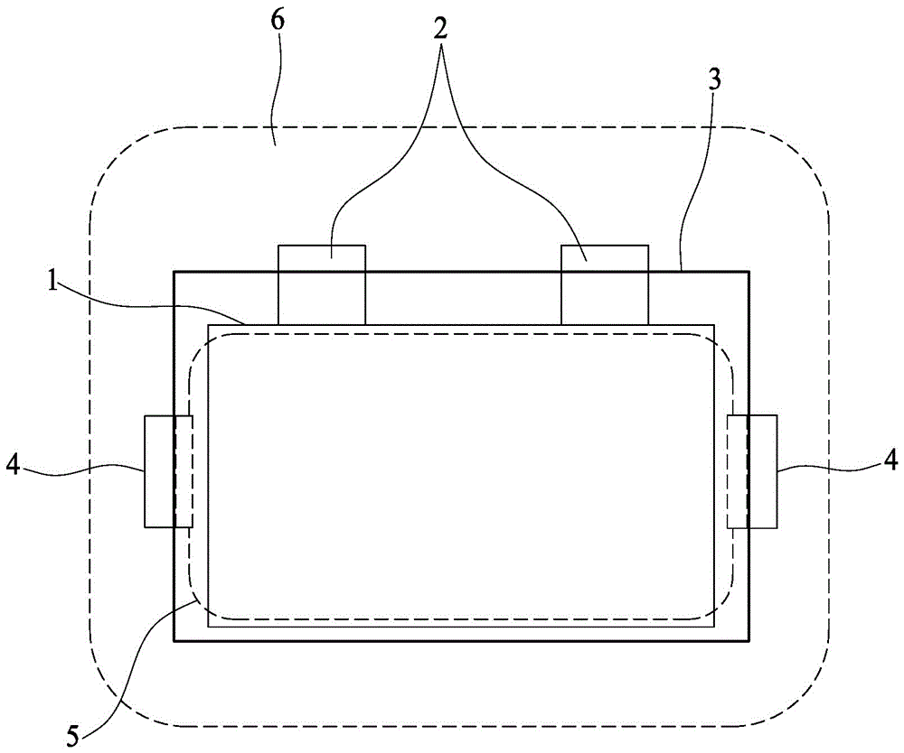
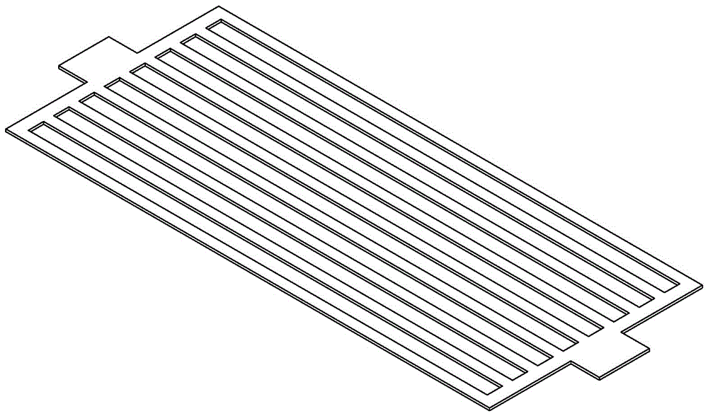
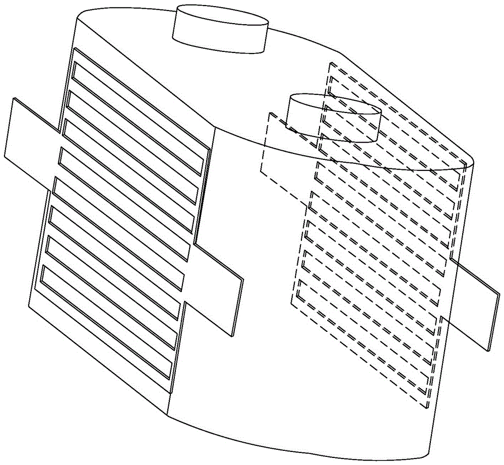
The invention discloses a rapid heating battery, which mainly comprises a battery shell, a battery core (comprising a positive plate, a negative plate, an isolation membrane, an electrolyte and the like), a metal foil body heating plate, a working terminal and a heating terminal, wherein the battery core is an electrochemical working system; the battery core completes conversion between electric energy and chemical energy in charging and discharging processes; the working terminal is a channel through which the electric energy and the chemical energy can pass in and out of the battery core; the metal foil body heating plate, the heating terminal and the battery shell are auxiliary components of the battery; the metal foil body heating plate is mainly used for heating the battery core; the heating terminal is a current channel of the metal foil body heating plate; and the battery shell is mainly used for packaging the battery core and the metal foil body heating plate. When the temperature of the battery core is relatively low, an external power supply provides the metal foil body heating plate with the electric energy through the heating terminal and the metal foil body heating plate converts the electric energy into heat energy for heating the battery core. The rapid heating battery has the advantages that the battery core and the metal foil body heating plate are packaged in the battery and the heating efficiency is high; and the working terminal of the battery core and the heating terminal of the metal foil body heating plate are mutually independent and input and output can be independently controlled.

Description

technical field [0001] The invention belongs to the field of chemical power sources, and relates to a battery heating technology, in particular to a battery technology using a metal foil heating plate to heat inside a battery cell. Background technique [0002] The dual pressure of energy shortage and environmental pollution has boosted the rapid development of chemical energy technology. At present, batteries have become the heart of electric products such as electric vehicles, mobile phones, and electric tools, and their performance directly affects the use of electric products. . Lithium-ion batteries have become the battery of choice for electrical products due to their advantages such as high energy density, long cycle life, and environmental friendliness. [0003] However, due to the decrease of material conductivity and chemical reaction rate in low temperature environment, the discharge power and discharge efficiency of lithium-ion batteries are seriously reduced, w...

Claims


Application Information

Patent Timeline
IPC IPC(8): H01M10/615H01M10/63
CPCH01M10/615H01M10/63Y02E60/10
Inventor 姜荣军兰成章巫扬勋
Owner XIAMEN HUARONG ENERGY TECH
Why Eureka
Try Eureka