Series energy storage balance apparatus and method with point-to-point path
A balancing device, point-to-point technology, applied in the direction of circuit devices, battery circuit devices, charge balancing circuits, etc., can solve the problems of long energy balancing path, inability to solve point-to-point direct energy transfer of energy storage units, low energy balancing efficiency, etc., to achieve The effect of short energy transmission path, fast speed and high efficiency
- Summary
- Abstract
- Description
- Claims
- Application Information
AI Technical Summary
Problems solved by technology
Method used
Image
Examples
specific Embodiment approach 1
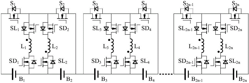
[0032] Specific implementation mode 1: No matter the number of energy storage units is 2n or 2n+1, for the first 2n energy storage units, the same group of energy storage units B 2n-1 and B 2n When performing equalization, the Buck-Boost working mode is adopted, that is, two energy storage cells, corresponding switching tubes, and coupled inductors form a Buck-Boost conversion circuit.
[0033] to combine Figure 4 , when the number of energy storage monomers is 2n, the energy storage monomer B in the second group 3 To energy storage unit B 4 The situation of transferring energy is used as an example to illustrate, and the switching tubes not mentioned are all in the off state. Here the energy storage unit B 3 , B 4 , switch tube S 3 , S 4 、SD 4 、SL 4 and coupled inductor L 4 Constitute a Buck-Boost conversion circuit. Switch tube SD 4 、SL 4 is always on, when the switch tube S 3 Open, S 4 When disconnected, B 3 to L 4 release energy, see the specific current ...
specific Embodiment approach 2
[0034] Specific implementation mode 2: Regardless of whether the number of energy storage cells is 2n or 2n+1, when the two cells in the group are balanced, the flyback working mode is adopted, that is, two energy storage cells and corresponding switching tubes and coupled inductors constitute Flyback conversion circuit. The energy storage unit that releases energy releases energy to the coupled inductor with a label different from its own in this group, and the coupled inductor after energy storage releases energy to the energy storage unit with the same label as itself.
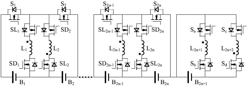
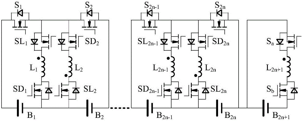
[0035] to combine Figure 5 , the number of energy storage units is 2n+1 in the first working mode, the energy storage unit B in the first group 2 To the n+1th group of energy storage unit B 2n+1 The situation of transferring energy is used as an example to illustrate, and the switching tubes not mentioned are all in the off state. Here the energy storage unit B 2 , B 2n+1 , switch SD 1 、SL 1 , S 2 ...
specific Embodiment approach 3
[0036] Specific implementation method three: no matter the number of energy storage cells is 2n or 2n+1, when one cell is balanced to multiple cells in the group, the flyback working mode is adopted, that is, multiple energy storage cells and corresponding switch tubes , The coupled inductor constitutes the flyback conversion circuit. The energy storage unit that releases energy releases energy to the coupled inductor with a label different from its own in this group, and the coupled inductor after energy storage releases energy to the energy storage unit with the same label as itself.
[0037] to combine Image 6 , in the first working mode where the number of energy storage units is 2n+1, the energy storage unit B in the n+1th group 2n+1 Energy storage unit B in group 1 1 and energy storage unit B in group n 2n The situation of transferring energy is used as an example to illustrate, and the switching tubes not mentioned are all in the off state. Here the energy storage ...
PUM
 Abstract
Description
Claims
Application Information
 - R&D
- Intellectual Property
- Life Sciences
- Materials
- Tech Scout
- Unparalleled Data Quality
- Higher Quality Content
- 60% Fewer Hallucinations
Browse by: Latest US Patents, China's latest patents, Technical Efficacy Thesaurus, Application Domain, Technology Topic, Popular Technical Reports.
© 2025 PatSnap. All rights reserved.Legal|Privacy policy|Modern Slavery Act Transparency Statement|Sitemap|About US| Contact US: help@patsnap.com


