Circuit board patch welding method for LED lamp

A patch welding and LED lamp technology, which is applied to the assembly of printed circuits, printed circuits, and printed circuit manufacturing of electrical components, can solve problems such as small size of patch components, failure of component performance, hidden dangers of product quality, etc., and achieve improvement SMT efficiency and accuracy, labor cost saving, simple placement process

Inactive Publication Date: 2017-03-22
SUZHOU HONGJIA ELECTRONICS CO LTD
View PDF5 Cites 8 Cited by
  • Summary
  • Abstract
  • Description
  • Claims
  • Application Information

AI Technical Summary

Problems solved by technology

[0002] At present, in the production process of standard products, especially when there are few SMD components on the circuit board of LED lamps, experimental production of new products, or when the production cycle is relatively urgent and cannot be outsourced for SMT processing, SMD components All use manual soldering, but this method has the following disadvantages: 1. Due to the small size of SMD components, small pads, and many pins, there are extremely high requirements for employees' soldering skills and proper soldering temperature, which is slightly difficult. Errors will lead to failure of component performance and hidden dangers in product quality; 2. Manual welding has low production efficiency and long construction period, which often affects the delivery cycle

Method used


Image

  • Circuit board patch welding method for LED lamp

Examples


Embodiment Construction

[0016] The following will clearly and completely describe the technical solutions in the embodiments of the present invention. Obviously, the described embodiments are only some of the embodiments of the present invention, rather than all the embodiments. Based on the embodiments of the present invention, all other embodiments obtained by persons of ordinary skill in the art without making creative efforts belong to the protection scope of the present invention.

[0017] like figure 1 As shown, embodiments of the present invention include:

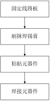
[0018] A circuit board patch welding method for LED lamps, comprising the following steps:

[0019] a. Fix the circuit board and fix the circuit board to be patched on the working platform;

[0020] b. Brush the solder paste, use the patch template, place the patch template on the upper surface of the circuit board, cover the holes on the patch template with solder paste and scrape evenly, and then tear off the patch template;

[0021] ...


PUM


Abstract

The invention discloses a circuit board patch welding method for an LED lamp. The method comprise steps of a, circuit board fixing; b, soldering paste brushing; c, component pasting; and d, component welding. The method is advantaged in that labor cost is saved, the mounting process is simple and direct, quality of welding components is guaranteed, patch welding efficiency is greatly improved, and improvement of efficiency and precision of patches is facilitated.

Description

technical field [0001] The invention relates to the technical field of LEDs, in particular to a circuit board patch welding method for LED lamps. Background technique [0002] At present, in the production process of standard products, especially when there are few SMD components on the circuit board of LED lamps, experimental production of new products, or when the production cycle is relatively urgent and cannot be outsourced for SMT processing, SMD components All use manual soldering, but this method has the following disadvantages: 1. Due to the small size of SMD components, small pads, and many pins, there are extremely high requirements for employees' soldering skills and proper soldering temperature, which is slightly difficult. Errors will lead to failure of component performance and hidden dangers in product quality; 2. Manual welding has low production efficiency and long construction period, which often affects the delivery cycle. Therefore just need to develop a...

Claims


Application Information

Patent Timeline
Patent Type & Authority Applications(China)
IPC IPC(8): H05K3/34
CPCH05K3/341H05K2203/04
Inventor 朱道田
Owner SUZHOU HONGJIA ELECTRONICS CO LTD
Why Eureka
Try Eureka