Damper device

A vibration damping device and anti-resonance technology, applied in transmission devices, fluid transmission devices, vibration suppression adjustment, etc., can solve the problems of reduced degrees of freedom, inability to obtain vibration attenuation effects, and difficulty in improving vibration attenuation performance.

Inactive Publication Date: 2017-03-22
AISIN AW CO LTD
View PDF5 Cites 3 Cited by
  • Summary
  • Abstract
  • Description
  • Claims
  • Application Information

AI Technical Summary

Problems solved by technology

Therefore, in the two-channel shock absorber of Patent Document 1, there is a worrying situation in which the setting of the vibration path B by adjusting the rigidity (spring constant) of each spring and the weight (moment of inertia) of the intermediate flange The degree of freedom of the natural frequency of C...

Method used


Image

  • Damper device
  • Damper device
  • Damper device

Examples


Embodiment Construction

[0015] Next, modes for implementing the invention of the present disclosure will be described with reference to the drawings.

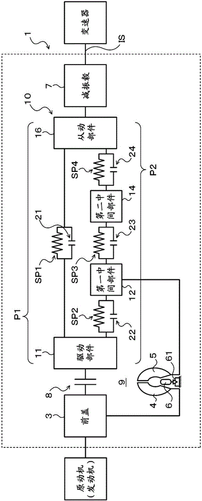
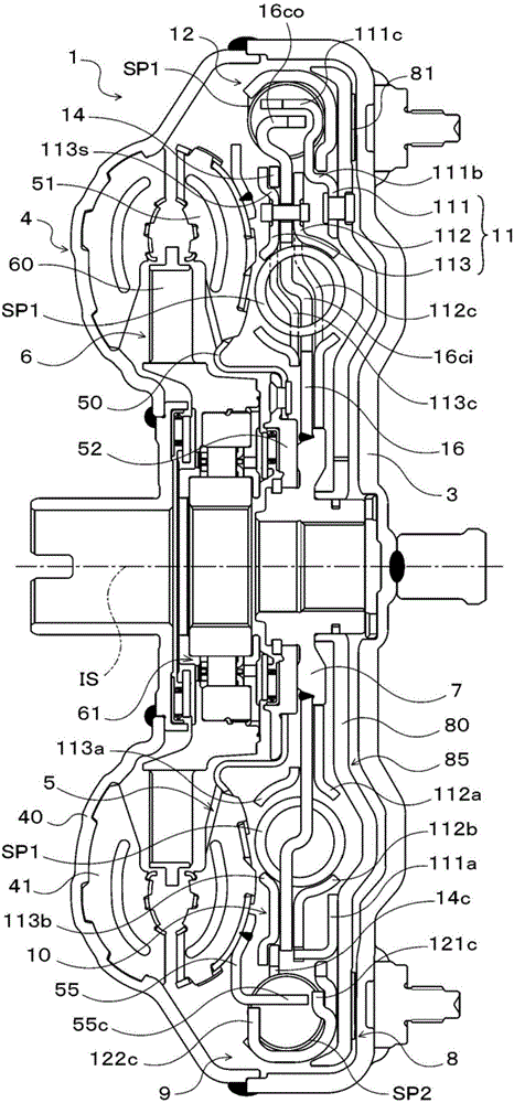
[0016] figure 1 is a schematic configuration diagram showing a starting device 1 including a vibration damping device 10 according to an embodiment of the present disclosure, figure 2 It is a sectional view showing the starting device 1 . The starting device 1 shown in these drawings is mounted on a vehicle equipped with an engine (internal combustion engine) as a prime mover. A pump impeller (input side fluid transmission member) 4 fixed to the front cover 3, a turbine wheel (output side fluid transmission member) 5 rotatable coaxially with the pump impeller 4, connected to a vibration damper 10 and fixed to an automatic transmission ( AT) or a continuously variable transmission (CVT) transmission input shaft IS, the damper hub 7, the lock-up clutch 8, etc. as power output components.

[0017] In addition, in the following description, "axial di...


PUM


Abstract

A damper device (10) is configured in such a manner that a first torque transmission path (P1) and a second torque transmission path (P2) which is provided in parallel with the first torque transmission path (P1) are arranged between a drive member (11) and a driven member (16). The first torque transmission path (P1) includes a first spring (SP1) for transmitting torque between the drive member (11) and the driven member (16). The second torque transmission path (P2) includes: first and second intermediate members (12, 14); a second spring (SP2) for transmitting torque between the drive member (11) and the first intermediate member (12); a third spring (SP3) for transmitting torque between the first intermediate member (12) and the second intermediate member (14); and a fourth spring (SP4) for transmitting torque between the second intermediate member (14) and the driven member (16).

Description

technical field [0001] The present disclosure relates to a vibration damping device including an input member and an output member, wherein power from an internal combustion engine is transmitted to the input member. Background technique [0002] Conventionally, a dual-channel damper used in connection with a torque converter is known as the above-mentioned damper (for example, refer to Patent Document 1). In this damping device, the vibration path from the engine and the lock-up clutch to the output hub is divided into two parallel vibration paths B and C, and the two vibration paths B and C respectively have a pair of springs and are arranged on the Separate middle flange between pair of springs. In addition, in order to make the resonance frequencies of the two vibration paths different, the turbine of the torque converter is coupled to the middle flange of the vibration path B, so that the natural frequency of the middle flange of the vibration path B is lower than the ...

Claims


Application Information

Patent Timeline
IPC IPC(8): F16H45/02F16D13/64F16F15/134
CPCF16H45/02F16F15/13469F16D3/12F16D25/0635F16D2300/22F16H2045/0205F16H2045/0247F16H2045/0278F16F15/13484F16H2045/0226F16F15/12366
Inventor 泷川由浩长井大树坂本贵生伊藤和广
Owner AISIN AW CO LTD
Why Eureka
Try Eureka