Automatic cutting device

An automatic cutting device and cutting technology, which are used in shearing devices, feeding devices, and cutting devices with nibbling action, etc., can solve the problems of cumbersome operation, many machine components, and low production efficiency.

Active Publication Date: 2017-03-29
FU DING ELECTRONICSAL TECH JIASHAN
View PDF5 Cites 14 Cited by
  • Summary
  • Abstract
  • Description
  • Claims
  • Application Information

AI Technical Summary

Problems solved by technology

[0003] Usually, the cutting process of metal shell strips generally goes through technological processes such as feeding, cutting, and blanking. The production process consumes a lot of manpower and increases produc

Method used


Image

  • Automatic cutting device
  • Automatic cutting device
  • Automatic cutting device

Examples


Embodiment Construction

[0017] The following will clearly and completely describe the technical solutions in the embodiments of the present invention with reference to the accompanying drawings in the embodiments of the present invention. Obviously, the described embodiments are only some, not all, embodiments of the present invention. Based on the embodiments of the present invention, all other embodiments obtained by persons of ordinary skill in the art without making creative efforts belong to the protection scope of the present invention.

[0018] It should be noted that when a component is said to be "fixed" to another component, it can be directly on the other component or there can also be an intervening component. When a component is said to be "connected" to another component, it may be directly connected to the other component or there may be intervening components at the same time. When a component is said to be "set on" another component, it may be set directly on the other component or t...


PUM


Abstract

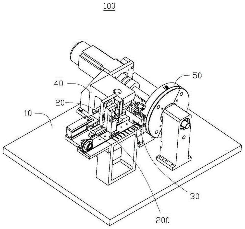
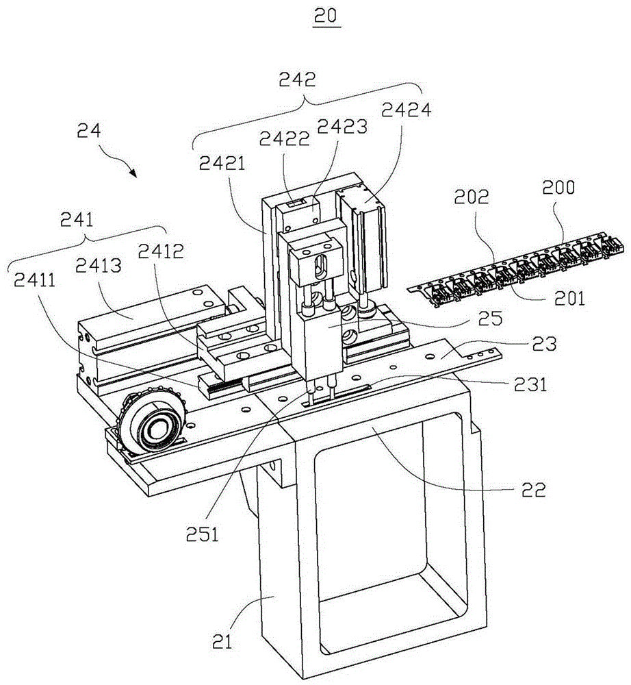
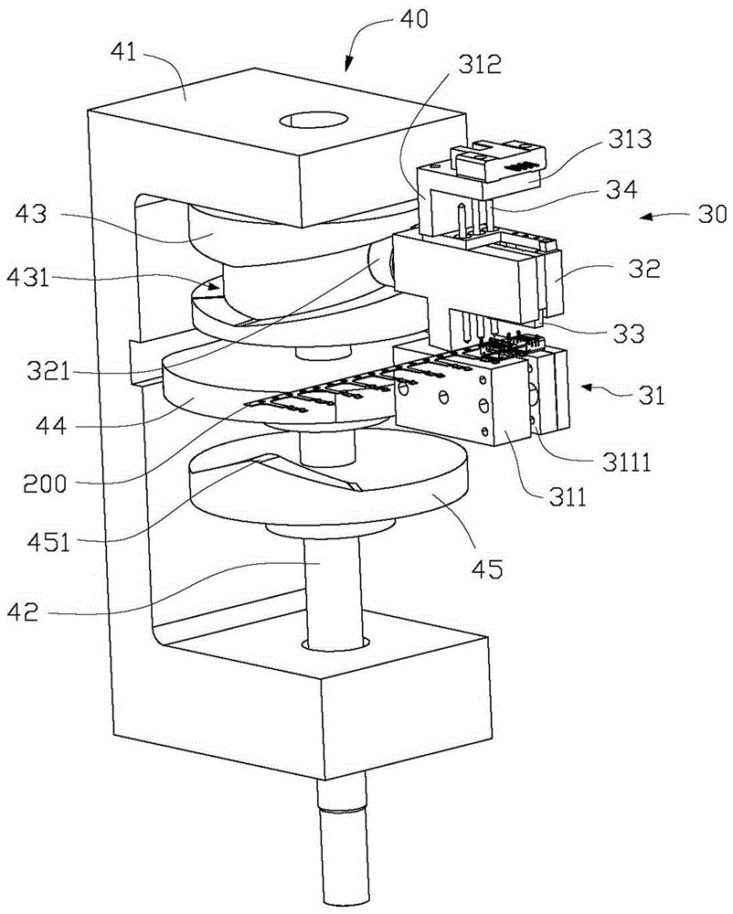
The invention discloses an automatic cutting device. The automatic cutting device comprises a feeding mechanism, a cutting mechanism, a cam mechanism and a discharging mechanism. The feeding mechanism is used for feeding materials to the cutting mechanism. The cutting mechanism comprises a mounting rack, a sliding block which is mounted on the mounting rack in a sliding mode and a tool which is mounted on the sliding block. The cam mechanism comprises a first cam, a second cam and a third cam. The first cam is provided with an annular groove, the second cam is an eccentric wheel, and the surface of the third cam is provided with protrusions. The first cam is used for driving the sliding block to move. The discharging mechanism comprises a discharging plate and a shifting assembly. The discharging plate comprises a plurality of feeding blocks and a plurality of discharging blocks. The shifting assembly comprises a shifting support, a feeding shifting rod and a discharging lever. The second cam is used for driving the feeding shifting rod to move. The feeding shifting rod is used for shifting the feeding blocks. The discharging lever abuts against the surface of the third cam. The protrusions are used for lifting the discharging lever. The discharging lever is used for pressing the discharging blocks.

Description

technical field [0001] The invention relates to a cutting device, in particular to an automatic cutting device for cutting material tapes. Background technique [0002] At present, in the field of electronics, the surface of small products is usually covered with a layer of metal casing to achieve the purpose of conducting electricity or protecting the product. The metal shell is usually manufactured by stamping the metal strip, that is, stamping the entire roll of metal strip to form a whole roll of metal shell strip, and then cutting according to the requirements, and then cutting the metal strip. The housing is mounted to small items. [0003] Usually, the cutting process of metal shell strips generally goes through technological processes such as feeding, cutting, and blanking. The production process consumes a lot of manpower and increases production costs; if automatic production is required, each process needs to use a cylinder Or the motor, resulting in relatively ...

Claims


Application Information

Patent Timeline
IPC IPC(8): B23Q7/00B23D33/02B23D33/00B23Q5/50B23D27/00
CPCB23D27/00B23D33/00B23D33/02B23Q5/50B23Q7/00
Inventor 吴伟伟丁峰蒋建光杨明陆
Owner FU DING ELECTRONICSAL TECH JIASHAN
Why Eureka
Try Eureka