Atomic layer deposition device

An atomic layer deposition and equipment technology, applied in the coating, metal material coating process, gaseous chemical plating and other directions, can solve the problems of reducing equipment cost, complex spray structure, unfavorable maintenance, etc., to improve manufacturing difficulty, simplify The internal structure and the effect of uniform and dense growth film

Active Publication Date: 2017-03-29
PIOTECH CO LTD
View PDF4 Cites 4 Cited by
  • Summary
  • Abstract
  • Description
  • Claims
  • Application Information

AI Technical Summary

Problems solved by technology

[0005] The purpose of the patent of the present invention is to solve the above-mentioned problems, and mainly solve the problems that the existing atomic layer deposition equipment has a complex spray structure, which is not conducive to maintenance and is not conducive to reducing equipment costs

Method used


Image

  • Atomic layer deposition device
  • Atomic layer deposition device
  • Atomic layer deposition device

Examples


Embodiment 1

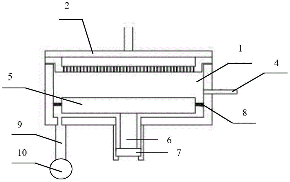
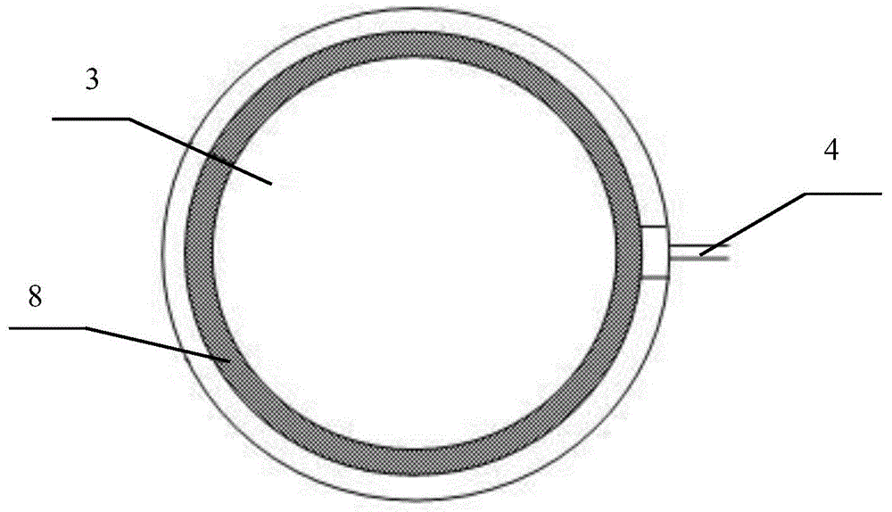
[0021] refer to Figure 1-2 , an atomic layer deposition equipment, comprising a reaction chamber 1, a spray device 2, a heating plate 3, the heating plate 3 includes a heating plate surface 5, a straight handle 6 and a heating plate base 7; the device also includes a side wall The air inlet pipeline 4, the restrictor bushing 8, the vacuum pipeline 9 and the mechanical pump 10; the spray device 2 is installed on the top of the reaction chamber 1, the heating plate surface 5, the straight handle 6 and the heating plate base 7 After being welded and fixed, the heating plate base 7 is installed on the bottom of the reaction chamber 1 with screws; the air inlet pipeline 4 on the side wall is connected to the reaction chamber 1 through screws or welding, and the outer edge of the flow-limiting bushing 8 is connected to the reaction chamber through screws. 1 is fixed inside, the heating plate 3 is not in contact with the restrictor bushing 8, one side of the vacuum pipeline 9 commun...

Embodiment 2

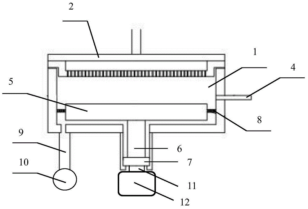
[0028] refer to Figure 2-3 , an atomic layer deposition device, the difference from Example 1 is that the heating plate base 7 is connected to the reaction chamber 1 by using screws under the reaction chamber to connect with the motor 12, and the heating plate base 7 It is connected with the base 11 of the motor 12 to realize that the heating plate base 7 can move up and down or rotate by itself in the reaction chamber 1 . During operation, when the mechanical pump 10 discharges the gas in the reaction chamber 1 through the vacuum pipeline 9, a vacuum will be formed inside the reaction chamber 1. The bottom will fit closely with the reaction chamber 1 so as to achieve the effect of sealing. Turn on the motor 12, move the heating plate 3 to the corresponding reaction position and fix it through the rise or fall of the heating plate base 7, rotate at a preset speed, and then pass a reaction gas through the nozzle on the top of the reaction chamber 1 The shower device 2 enters...


PUM


Abstract

The invention discloses an atomic layer deposition device. The problems that a spraying structure of existing atomic layer deposition equipment is complex, and maintaining and lowering of equipment cost are not facilitated need to be solved. The atomic layer deposition device is provided and comprises a reaction cavity, a spraying device and a heating disc. The heating disc comprises a heating disc face, a straight shank and a heating disc base. The device further comprises an air inlet pipeline on the side wall, a flow limiting lining, a vacuum pipeline and a mechanical pump. Through introduction of the air inlet pipeline on the side wall, the complex structure of the spraying device is greatly simplified, and the universality and maintainability of the device can be improved.

Description

technical field [0001] The invention relates to atomic layer deposition equipment, which belongs to the technical field of semiconductor thin film deposition application and manufacture. Background technique [0002] The atomic layer deposition equipment uses two or more different reactive gases to alternately enter the reaction chamber and grow a continuous atomic-scale thin film on the surface of the substrate through surface reaction, which requires each reactive gas to enter the reaction chamber alternately. Before the latter gas enters, the former gas must be thoroughly purged in the reaction chamber, in this way the possibility of chemical vapor deposition in the reaction chamber is reduced. [0003] Mixing chemical vapor deposition in atomic layer deposition will have many adverse effects, such as poor uniformity of the deposited film, difficulty in controlling the thickness of the deposited film, and a large number of particles. Traditional semiconductor equipment u...

Claims


Application Information

Patent Timeline
Patent Type & Authority Applications(China)
IPC IPC(8): C23C16/455
Inventor 初春齐平高超
Owner PIOTECH CO LTD
Why Eureka
Try Eureka