An internal card type hydraulic cylinder for tensioning deep buried anchors

A technology of hydraulic cylinders and deep-buried anchors, which is used in fluid pressure actuating devices, construction, bridge construction, etc., can solve the problems of inconvenient extending into the anchor hole, time-consuming and laborious threading of steel strands, and heavy tool anchors. The effect of anchoring reliability, reducing labor intensity and reducing bridge cost

Active Publication Date: 2019-04-30
襄阳中铁宏吉工程技术有限公司
View PDF8 Cites 0 Cited by
  • Summary
  • Abstract
  • Description
  • Claims
  • Application Information

AI Technical Summary

Problems solved by technology

[0002] The existing tension structure of the through-type hydraulic cylinder is as follows: figure 1 As shown, in the bridge prestressed construction, the steel strand 10 passes through the anchor plate 9 installed in the concrete beam and the working anchor plate 11 installed in the anchor hole, passes through the limiting plate 12, lengthens Sleeve 16, hydraulic cylinder interior, tool anchor gasket ring 17, tool anchor 15; when tensioning, one end of the hydraulic cylinder withstands the extended sleeve 16 and does not move, and the piston 4 of the hydraulic cylinder drives the tool anchor gasket ring 17 and tool anchor 15 to move outward, and the tool anchor 15 moves outward. The anchor 15 clamps the steel strand 10 and moves outward together. After reaching the specified force and elongation value, the piston 4 returns, and the steel strand 10 is anchored by the working anchor plate 11, and no longer retracts with the piston 4, thereby realizing prestressed tension. Pull; in order to ensure that the steel strands are stretched, the steel strands should be reserved for passing through the length of the limit plate 12, the extension sleeve 16, the hydraulic cylinder, the tool anchor pad ring 17, the tool anchor 15, and the steel strand 10 is connected from the anchor pad 9 Generally, a process length of about 800mm should be reserved from the end face to the outside of the beam; after tensioning, the excess steel strands 20∽30mm away from the 11th end of the working anchor plate should be cut off so as to seal the anchor, resulting in waste of steel strands
In order to save steel strands, shorten the distance between the tool anchor 15 and the limit plate 12; the existing technology is to place the tool anchor 15 inside the hydraulic cylinder, and the tool anchor 15 is connected to the through-hole sleeve of the hydraulic cylinder by threads 5; when tensioning the multi-hole group anchor, install the working anchor plate 11 in the anchor hole about 200mm away from the beam end. The anchor hole is a deep pit with a diameter of 300~400mm and a depth of 200mm. The outer diameter of the hydraulic cylinder is large and the oil inlet / return joints are installed at the left and right beam ends, which is inconvenient to extend into the anchor hole; when tensioning, an extension sleeve 16 is installed between the limit plate 12 and the hydraulic cylinder, and the length is 120~ 140mm, the steel strand passing through the limit plate 12, enters the tool anchor 15 through the extension sleeve 16, the sight is not good, and it takes time and effort to thread the steel strand; there are generally several specifications of anchors at the beam end, and the tool anchor adopts 70~ The 80mm long 3mm pitch turnbuckle is screwed into the through sleeve 5 of the hydraulic cylinder, which is inconvenient to replace. In addition, the tool anchors are heavy, so it is difficult to handle with care after replacement, and the outer turnbuckle is easily damaged, causing the tool anchor to spin. The combined length does not meet the requirements, resulting in a reduction in the life of the tool anchor
During bridge prestressing construction, in order to ensure that the tension at both ends of the bridge is basically the same, and to control the tension at the same time, it is necessary to measure the elongation of the steel strand. The elongation of the steel strand is generally converted by measuring the extension of the piston 4. The tool The built-in anchor 15 is inconsistent with the installation method of ordinary through-hole hydraulic cylinders when tensioning, and the piston 4 is close to the beam end. When tensioning, the piston 4 does not move and the cylinder barrel 3 moves outward. Therefore, it is inconvenient to measure the length of the piston 4, which is time-consuming and laborious. The above reasons are not widely used in the market

Method used


Image

  • An internal card type hydraulic cylinder for tensioning deep buried anchors
  • An internal card type hydraulic cylinder for tensioning deep buried anchors
  • An internal card type hydraulic cylinder for tensioning deep buried anchors

Examples


Embodiment Construction

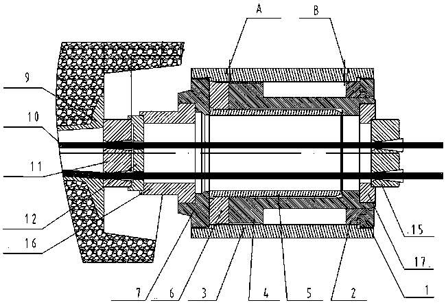
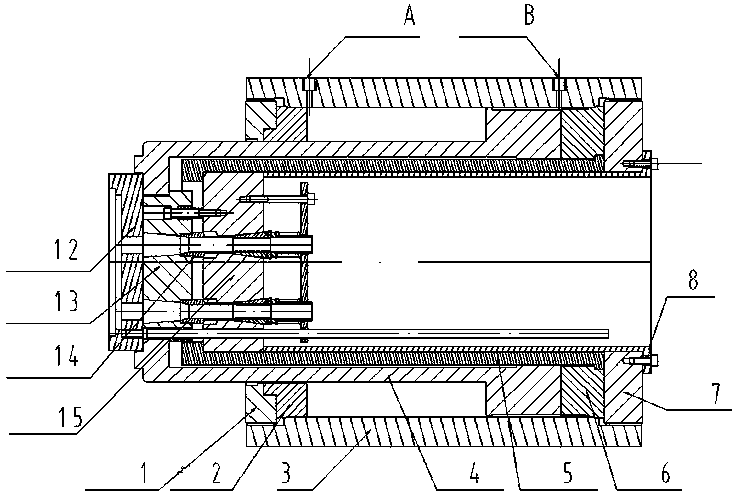
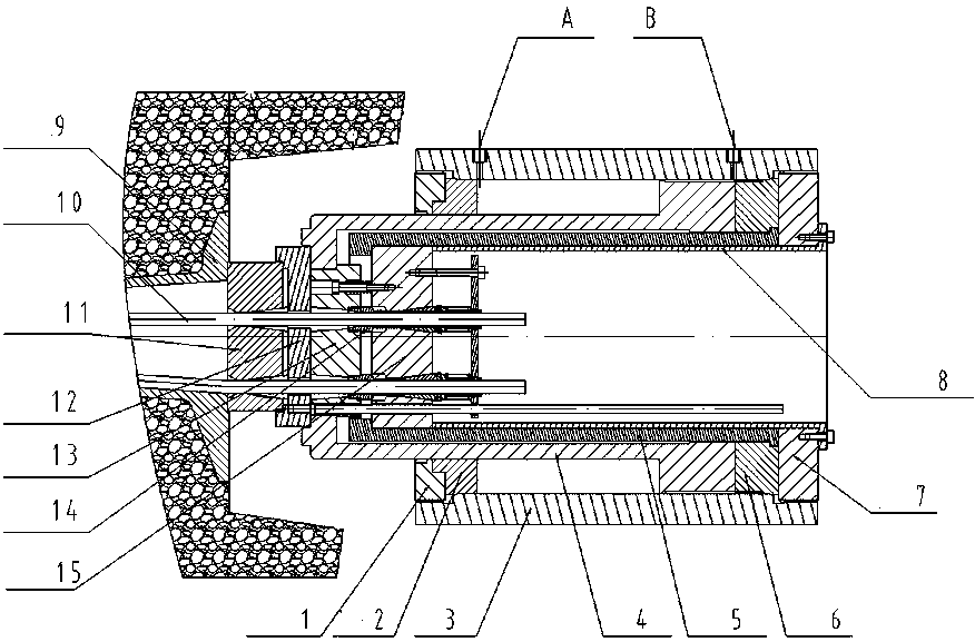
[0014] Such as figure 1 As shown, the present invention includes a limiting plate 12 and a tool anchor 15, and a hydraulic cylinder composed of a cylinder 3, a piston 4, a front end cover 1, a front sealing ring 1, a rear sealing ring 6, and a rear end cover 7; the piston 4 is installed In the middle position inside the cylinder barrel 3, the piston rod of the piston 4 protrudes from the front end cover 1, and the length is more than 100mm, and the inner hole end of the piston rod end has a step; Ring 1, rear seal ring 6, rear end cover 7, a through sleeve 5 is installed inside the piston 4, the through sleeve 5 and the hydraulic cylinder form an internal card type hydraulic cylinder for deep buried anchors; the through sleeve 5 is a A cylinder concentric with the piston 4 of the hydraulic cylinder. A step is provided on the inner circle of the cylinder at the end close to the front end cover 1. A tool anchor 15 is placed on the end close to the front end cover 1 of the hydrau...


PUM


Abstract

The invention discloses an internal clamping type hydraulic cylinder for stretching a deeply buried anchor and relates to an internal clamping type hydraulic cylinder for stretching an anchorage device. The problems that according to existing stretching devices, tool anchors are placed in hydraulic cylinders, steel strands penetrate through limiting plates and enter the tool anchors through lengthened sleeves, steel strand threading wastes time and energy, the tool anchors are heavy, and outer screws are prone to being damaged during carrying are mainly solved. The internal clamping type hydraulic cylinder comprises a hydraulic cylinder body, a hollow wrap arranged in a hydraulic cylinder piston, a limiting plate and a tool anchor. The internal clamping type hydraulic cylinder is characterized in that a piston rod of the hydraulic cylinder piston and the hollow wrap extend out of a hydraulic cylinder front end cover, the tool anchor is arranged in the extending end of the hollow wrap, and a tool anchor spacer sleeve is fixed in the hollow wrap; one end of the tool anchor spacer sleeve is jacked on the tool anchor, and the other end of the tool anchor spacer sleeve is fixed to the end face of a hydraulic cylinder rear end cover; and a separator plate and a pushing sleeve are mounted between the limiting plate and the tool anchor. The tool anchor is convenient to mount and take down, the working efficiency is high, the anchoring reliability is high, and the steel strand positioning and hole penetrating speeds are high.

Description

technical field [0001] The invention relates to a piercing type hydraulic cylinder, in particular to an internal clip type hydraulic cylinder for tensioning deep buried anchors. Background technique [0002] The existing tension structure of the through-type hydraulic cylinder is as follows: figure 1 As shown, in the bridge prestressed construction, the steel strand 10 passes through the anchor plate 9 installed in the concrete beam and the working anchor plate 11 installed in the anchor hole, passes through the limiting plate 12, lengthens Sleeve 16, hydraulic cylinder interior, tool anchor gasket ring 17, tool anchor 15; when tensioning, one end of the hydraulic cylinder withstands the extended sleeve 16 and does not move, and the piston 4 of the hydraulic cylinder drives the tool anchor gasket ring 17 and tool anchor 15 to move outward, and the tool anchor 15 moves outward. The anchor 15 clamps the steel strand 10 and moves outward together. After reaching the specified ...

Claims


Application Information

Patent Timeline
Patent Type & Authority Patents(China)
IPC IPC(8): F15B15/14F15B15/20E01D21/00E01D101/28
Inventor 易爱军李典计周宇张永超范凌
Owner 襄阳中铁宏吉工程技术有限公司
Why Eureka
Try Eureka