
Frequency-conversion electromagnetic heating energy-saving system

An energy-saving system, electromagnetic technology, applied in water heaters, fluid heaters, lighting and heating equipment, etc., can solve the problems of difficult and accurate temperature control, resistance wire burnout, short service life, etc., to achieve real-time accurate temperature control, The effect of small thermal retardation and uniform temperature

Inactive Publication Date: 2017-03-29
于永年
View PDF7 Cites 2 Cited by
  • Summary
  • Abstract
  • Description
  • Claims
  • Application Information

AI Technical Summary

Problems solved by technology

[0002] The existing electromagnetic heating technology is not very mature, and has the following disadvantages: large heat loss, the traditional electric heating industry generally adopts resistance wire, electric heating rod, electrode and quartz heating methods, and this traditional heating method, its thermal efficiency In comparison, resistance wires, electric heating rods, electrodes and quartz mainly generate heat by themselves after being energized and then transfer the heat to the barrel or container, thereby heating the objects. The heat utilization rate of this heating effect is the highest. Only about 50%-80%, heat loss is as high as 20%-50% or more; short service life: large amount of maintenance
Because the electric heating tube uses resistance wire, electric heating rod, electrode and quartz to generate heat, its heating temperature is as high as about 200 degrees, the thermal lag is large, and it is difficult to accurately control the temperature. The resistance wire, electric heating rod, electrode and quartz are easy to burn out due to high temperature aging

Method used


Image

  • Frequency-conversion electromagnetic heating energy-saving system
  • Frequency-conversion electromagnetic heating energy-saving system

Examples


Embodiment Construction

[0014] In order to clearly understand the technical solution of the present invention, its detailed structure will be presented in the following description. Obviously, the implementation of the embodiments of the invention is not limited to specific details familiar to those skilled in the art. The preferred embodiments of the present invention are described in detail below, and there may be other implementations besides those described in detail.

[0015] The present invention will be described in further detail below in conjunction with the accompanying drawings and embodiments.

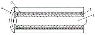
[0016] combine figure 1 and figure 2 , the figure discloses a frequency conversion electromagnetic heating energy saving system. The frequency conversion electromagnetic heating energy saving system includes a pipeline 1, a heating coil 3, an insulating and heat insulating medium layer 2, a thermal sensor, a frequency conversion module, and a cloud control module. The outer wall of the pipeline...


PUM


Abstract

The invention discloses a frequency-conversion electromagnetic heating energy-saving system. The frequency-conversion electromagnetic heating energy-saving system comprises a pipeline, a heating coil, an insulation and thermal insulation dielectric layer, a heat sensor, a frequency-conversion module and a cloud control module. The insulation and thermal insulation dielectric layer is wound on the outer wall of the pipeline; the high temperature resistance coil is arranged outside the insulation and thermal insulation dielectric layer; the frequency-conversion module is connected with the two ends of the coil; the frequency-conversion module is connected to the cloud control module; one end of the heat sensor is connected with the outer wall of the pipeline and the other end of the heat sensor is connected to the cloud control module; and liquid is placed in the pipeline. According to the technical scheme, high efficiency and energy saving are achieved, the service life is long, safety and reliability are realized, temperature control is accurate, and the insulation property is good.

Description

technical field [0001] The invention relates to the technical field of electronic communication, in particular to a frequency conversion electromagnetic heating energy-saving system. Background technique [0002] The existing electromagnetic heating technology is not very mature, and has the following disadvantages: large heat loss, the traditional electric heating industry generally adopts resistance wire, electric heating rod, electrode and quartz heating methods, and this traditional heating method, its thermal efficiency In comparison, resistance wires, electric heating rods, electrodes and quartz mainly generate heat by themselves after being energized and then transfer the heat to the barrel or container, thereby heating the objects. The heat utilization rate of this heating effect is the highest. Only about 50%-80%, heat loss as high as 20%-50% or more; short service life: large amount of maintenance. Because the electric heating tube uses resistance wire, electric h...

Claims


Application Information

Patent Timeline
Patent Type & Authority Applications(China)
IPC IPC(8): F24H1/14F24H9/18F24H9/20
CPCF24H1/142F24H9/1818F24H9/2028F24H2250/08
Inventor 于永年
Owner 于永年
Learn More