Interference system, multilayer interferometer therefor, single layer interferometer therefor and bar-shaped interferometer therefor

An interferometric system and interferometer technology, applied in instruments, measuring devices, optical devices, etc., can solve the problems of large volume, small number of channels, and the phase is easily affected by the environment, and achieve the effect of increasing the number of channels

Active Publication Date: 2017-03-29
UNIV OF SCI & TECH OF CHINA
View PDF7 Cites 0 Cited by
  • Summary
  • Abstract
  • Description
  • Claims
  • Application Information

AI Technical Summary

Problems solved by technology

[0003] There are many ways to implement multi-channel optical interferometers. There are two common multi-channel optical interferometers. The first one is a free-space interferometer built with separate block optical components. The advantage is that it can Technology achieves ultra-low loss, usually less than 0.1dB. The disadvantage is that it is bulky, the number of channels is small, and the phase is easily affected by the environment. The second is the optical fiber or optical waveguide integrated interferometer. The phase is very stable, but the disadvantage is that the insertion loss is relatively large, usually exceeding 3dB

Method used


Image

  • Interference system, multilayer interferometer therefor, single layer interferometer therefor and bar-shaped interferometer therefor
  • Interference system, multilayer interferometer therefor, single layer interferometer therefor and bar-shaped interferometer therefor
  • Interference system, multilayer interferometer therefor, single layer interferometer therefor and bar-shaped interferometer therefor

Examples


Embodiment Construction

[0046] The following will clearly and completely describe the technical solutions in the embodiments of the present invention with reference to the accompanying drawings in the embodiments of the present invention. Obviously, the described embodiments are only some, not all, embodiments of the present invention. Based on the embodiments of the present invention, all other embodiments obtained by persons of ordinary skill in the art without making creative efforts belong to the protection scope of the present invention.

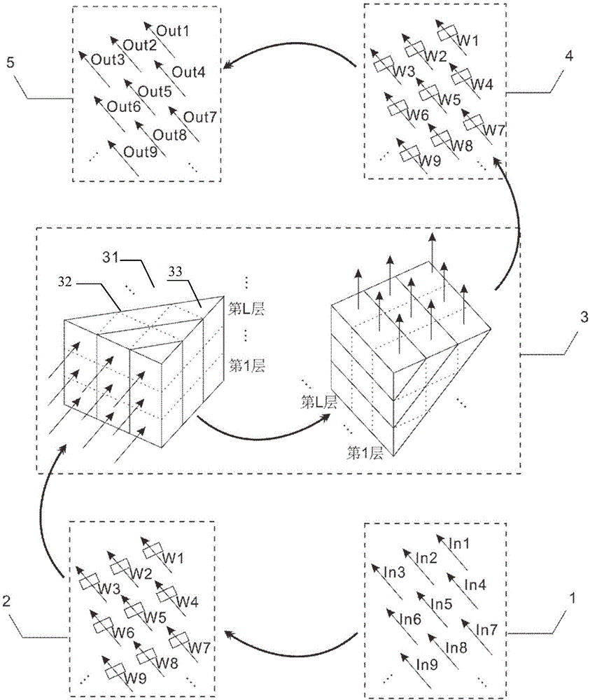
[0047] In the prior art, for the interference system, both the triangular beam splitter arrangement and the rectangular beam splitter arrangement have been implemented in the waveguide integrated interferometer. But in free-space interferometers, there is currently no way to implement an interferometric system due to the bulky size and phase instability of free-space interferometers.

[0048]In cutting-edge fields such as precision measurement and quantum info...


PUM


Abstract

The invention discloses an interference system comprising an input end, a first multiple freedom degree interference module, a path interference module, a second multiple freedom degree interference module and an output end, wherein the input end is used for inputting multipath light beams, the multiple freedom degree interference module and the second multiple freedom degree interference module are used for interference among different degrees of freedom at the same path, the path interference module is used for interference among different degrees of freedom at different paths, and the output end is used for outputting the multipath light beams; the light beams input via the input end are emitted out after orderly going through the first multiple freedom degree interference module, the path interference module, the second multiple freedom degree interference module and the output end. The number of passageways can be increased in the interference system, and any input passageway can be communicated with any output passageway.

Description

technical field [0001] The invention relates to the technical field of optical signal processing, and more specifically relates to an interference system and its multi-layer interferometer, single-layer interferometer and strip interferometer. Background technique [0002] Optical interferometers can be divided into two categories: single-channel optical interferometers and multi-channel optical interferometers. The difference between single-channel optical interferometers and multi-channel optical interferometers lies in whether the interfering light waves pass through multiple channels. For example, single-channel optical interferometers include equal thickness interferometers and Sagnac interferometers, multi-channel optical interferometers include Michelson interferometers and Mach-Zehnder interferometers, etc. . Compared with single-channel optical interferometer, multi-channel optical interferometer has many advantages. For example, in optical communication, it can be...

Claims


Application Information

Patent Timeline
Patent Type & Authority Applications(China)
IPC IPC(8): G01B9/02
CPCG01B9/02027
Inventor 苏祖恩陆朝阳王辉贺煜庄思源潘建伟
Owner UNIV OF SCI & TECH OF CHINA
Why Eureka
Try Eureka