Semi-automatic assembly machine for precision valve

A semi-automatic and machine technology, applied in the direction of manufacturing tools, metal processing, metal processing equipment, etc., can solve the problems of difficult to ensure the verticality and depth of the valve, high product failure rate, low efficiency, etc., to achieve high assembly efficiency and assembly. The effect of quality improvement, simple and convenient operation

Active Publication Date: 2017-04-05
江门格兰达物联装备有限公司
9 Cites 0 Cited by

AI-Extracted Technical Summary

Problems solved by technology

[0002] At present, when precision valves are produced in the market, most of the valves are manually loaded into the valve body, and then the valve is pressed in by a manual p...

Method used

[0048] The frame assembly mainly includes a profile frame 45, a sealing plate 46, a hinge 11, an electrical mounting plate 47, an electric box door 48, a foot cup 49 and casters 50. The main body of the frame is assembled from profiles, with sealing plates 46 installed on ...

Abstract

The invention provides a semi-automatic assembly machine for a precision valve. The machine comprises a positioning press component (2), a positioning fixture component (3) and an electrical component (4). The positioning press component (2) comprises a valve positioning component and a press component. The press component comprises a bracket, a press cylinder (17), a press bar (18), a lift cylinder (21) and a first linear guide rail (14). The valve positioning component is located below the press cylinder. The valve positioning component comprises a fixation frame, a preload component and a three-jaw cylinder (33) in a hollow structure. The positioning fixture component is located below the valve positioning component. The positioning fixture component comprises a large platen (41), a fixture carrier plate (40) and a fixture push cylinder (35). The electrical component is used for driving the press cylinder, the lift cylinder, the three-jaw cylinder and the fixture push cylinder to move. The semi-automatic assembly machine provided by the invention has the advantages of high assembly efficiency, reduced assembled product defective rate and simple and convenient operation.

Application Domain

Technology Topic

Image

  • Semi-automatic assembly machine for precision valve
  • Semi-automatic assembly machine for precision valve
  • Semi-automatic assembly machine for precision valve

Examples

  • Experimental program(1)

Example Embodiment

[0041] In order to make the above objects, features and advantages of the present invention more comprehensible, the present invention will be further described in detail below in conjunction with the accompanying drawings and specific embodiments.
[0042] Reference herein to "one embodiment" or "an embodiment" refers to a particular feature, structure or characteristic that can be included in at least one implementation of the present invention. "In one embodiment" appearing in different places in this specification does not all refer to the same embodiment, nor is it a separate or selective embodiment that is mutually exclusive with other embodiments.
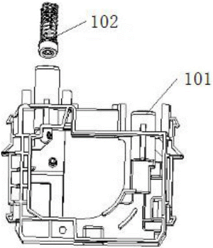
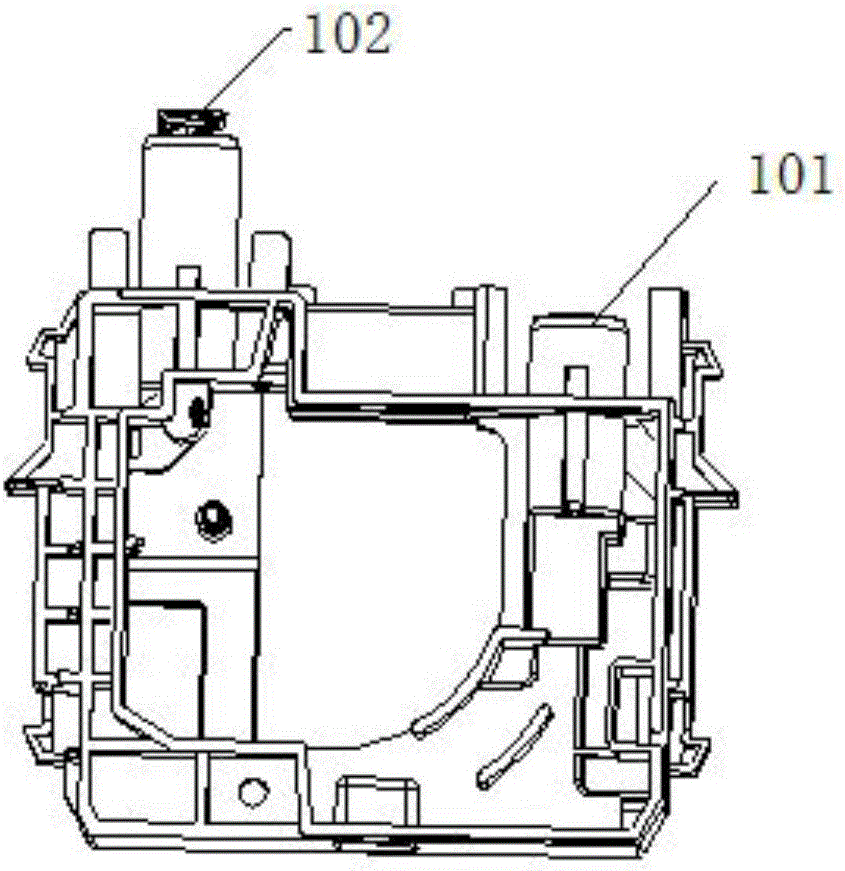
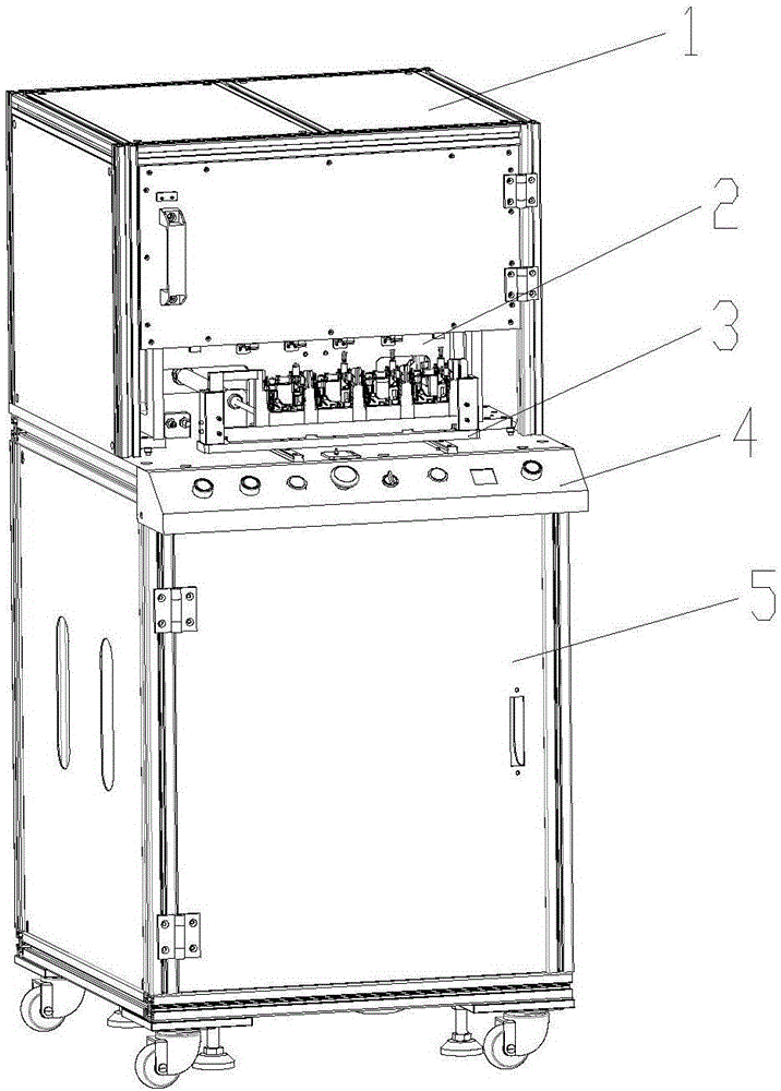
[0043] see Figure 1(a) to Figure 2(l), wherein, Fig. 1 (a) is the state diagram before the precision valve assembly of the present invention; Fig. 1 (b) is the state diagram after the precision valve assembly of the present invention; Three-dimensional schematic diagram; Figure 2(b) is a three-dimensional schematic diagram of the safety cover of the assembled machine tool; Figure 2(c) is a perspective schematic diagram of the front of the pressing assembly; Figure 2(d) is a perspective schematic diagram of the back of the pressing assembly; Figure 2(e) is a perspective view of the valve Figure 2(f) is a perspective view of a pre-pressing component; Figure 2(g) is a perspective view of a three-jaw cylinder; Figure 2(h) is a schematic view of the combination of positioning and pressing components; Figure 2(i) is a schematic view of Figure 2 (h) A three-dimensional schematic diagram of the back structure; FIG. 2(j) is a three-dimensional schematic diagram of the positioning fixture assembly; FIG. 2(k) is a three-dimensional schematic diagram of the rack; FIG. 2(l) is a three-dimensional schematic diagram of the operating components. Depend on Figure 1(a) to Figure 2(l) As shown, the precision valve semi-automatic assembly tool of the present invention mainly includes a safety cover 1 , a positioning pressing assembly 2 , a positioning jig assembly 3 , an electrical system 4 and a frame assembly 5 . The positioning and pressing assembly 2 includes a valve positioning assembly and a pressing assembly.
[0044] The safety cover 1 mainly includes a transparent sealing plate 6 , a safety cover profile frame 7 , a safety door lock 8 , a handle 9 , a safety door 10 and a hinge 11 . Safety cover 1 back side, left and right sides and top are fixed on profile frame 7 by transparent sealing plate 6, and safety door 10 rotates and cooperates with safety cover profile frame 7 by hinge 11, and when opening safety door 10, equipment can stop running, and closes the door again. After pressing the left start button 52 and the right start button 59 simultaneously, the device continues to run.
[0045] The pressing assembly mainly includes a pressing cylinder mounting plate 12, a support plate 13, a first linear guide rail 14, a lifting cylinder mounting plate 15, a pressing assembly mounting block 16, a pressing cylinder 17, a pressure rod 18, a first optical fiber 19, The first optical fiber installation plate 20 , the lifting cylinder 21 and the first buffer limit assembly 22 . Four pressing cylinders 17 are fixedly installed with the pressing cylinder installation plate 12 that is fixedly installed by two support plates 13, and the piston rod front end of pressing cylinder 17 is fixedly equipped with compression rod 18, and compression rod 18 passes linear bearing 31, and Stretch into the three-jaw air cylinder 33 of hollow structure, linear bearing 31 can be correctly guided to pressure rod 18, guarantees that pressure rod 18 can be pressed down vertically when pressing cylinder 17 stretches out, and lifting cylinder mounting plate 15 is fixedly mounted on two pressure rods. On the two support plates 13 fixedly installed by the component mounting block 16, two first linear guide rails 14 are installed on the front side of the lifting cylinder mounting plate 15, and the lifting cylinder 21 and the first buffer limit assembly 22 are installed on the back side. An optical fiber 19 is fixedly installed through the first optical fiber mounting plate 20 and the lifting cylinder mounting plate 15. When the product is pushed in place, the first optical fiber 19 can detect whether the product valve is present and whether it is properly placed. It will pause and give an alarm prompt. After manual processing, press the left start button and the right start button, and the device will continue to run.
[0046] The valve positioning assembly mainly includes guide rail connecting block 23, three-jaw cylinder mounting plate 24, linear guide rail mounting plate 25, second linear guide rail 26, slider connecting plate 27, pressure block 28, limit block 29, guide rod 30, linear bearing 31, spring 32, three claw cylinder 33 and clip block 34. The first linear guide rail 14 is slidably connected with the guide rail connecting block 23 fixed on the three-jaw cylinder mounting plate 24, which can correctly guide the three-jaw cylinder mounting plate 24 to move up and down, so as to ensure that the three-jaw cylinder 33 is in the action process of the lifting cylinder 21 No offset occurs. Four three-claw cylinders 33 are installed on the bottom surface of the three-claw cylinder mounting plate 24, and three clamp blocks 34 are fixedly installed on each three-claw cylinder 33. Carry out piloting, and ensure that there is a 0.05MM gap with the outer circle of the valve, so as to avoid damage to the surface of the valve due to friction between the valve and the clamp block 34 during pressing. The three-claw cylinder 33 is a hollow structure, and the pressure rod 18 can pass through the center of the cylinder. Four sets of pre-loading components are installed on the bottom surface of the three-claw cylinder mounting plate 24. The second linear guide rail 26 is fixed on the linear guide rail mounting plate, the slider connecting plate 27 is slidingly connected with the linear guide rail 26, the upper end of the slider connection 27 is fixed with a guide rod 30, the lower end is fixed with a pressure block 28, and the spring 32 is elastic. Connected between the three-jaw cylinder 24 and the slider connecting plate 27, the spring 32 is limited by the guide rod 30 to pop up. When the lifting cylinder 21 drives the valve positioning assembly to descend, the pressure block 28 of the pre-pressing assembly pre-presses the product valve body and Positioning, the valve body is positioned through the V-shaped groove on the briquetting block 28 to ensure that the valve body will not shake and shift when the valve is pressed together.
[0047] The positioning jig assembly mainly includes a jig push cylinder 35, a push cylinder installation block 36, a jig 37, a jig limit block 38, a ball plunger 39, a jig carrier plate 40, a large platen 41, and a second buffer limiter. bit assembly 60 , second optical fiber 42 , second optical fiber mounting plate 43 , and third linear guide rail 44 . The jig pushing cylinder 35 is fixedly installed with the push cylinder installation block 36 installed on the large platen 41, the front end of the piston rod of the jig pushing cylinder 35 is fixedly installed with the jig carrier plate 40, and the jig carrier plate 40 is fixedly installed with the jig carrier plate 40. The third linear guide rail 44 on the large platen 41 is slidably connected, so that the jig carrier 40 can move back and forth along the large platen 41 without offset. The jig limiter 38 is installed on both sides of the top surface of the jig carrier plate 40, the front and side of the jig limiter 38 are fixed with a ball plunger 39, and the jig 37 is positioned through the groove of the jig limiter 38 , and tighten the jig 37 by the ball plunger. The second optical fiber 42 is fixed to the large platen 41 through the second optical fiber mounting plate 43, and the position is located under the jig carrier 40. When the left start button and the right start button of the device are pressed, the second optical fiber 42 will automatically judge the jig If there is no 37, it will continue to operate according to the normal process. If it is detected that there is no fixture 37, the equipment will alarm and stop. Put the fixture 37 and press the double start button again to continue the operation.
[0048] The frame assembly mainly includes profile frame 45, sealing plate 46, hinge 11, electrical installation plate 47, electric box door 48, foot cup 49 and caster 50. The main body of the frame is assembled from profiles, with sealing plates 46 installed on both sides and the back, and the internal electrical installation plate 47 is used to install electrical components. Caster 50 and foot cup 49 are arranged, and caster 50 is convenient to equipment moving and carrying, and foot cup 49 is used for supporting fixed equipment.
[0049] The electrical components mainly include button box 51, left start button 52, reset button 53, single action button 54, emergency stop button 55, power knob 56, buzzer 57, alarm code display 58 and right start button 59. The button box 51 is fixed with the frame assembly 5. During normal work, both hands press the left start button 52 and the right start button 59 simultaneously. When a fault occurs, the emergency stop button 55 can be pressed to stop the operation of the equipment. , activating the reset button 53 is used to restore the device to the initial state. The alarm code display screen 58 is used to display the fault information codes when reporting to the police, and the cause of the alarm can be understood by the codes, which helps to solve problems quickly. When the single-action button 54 is pressed, a single-step action can be performed, and each time it is pressed, one step of action will be performed in turn. When changing different models of products, it is helpful for equipment debugging.
[0050] The working process of the semi-automatic assembly tool of the present invention is as follows: manually put the product valve body to be assembled into the jig 37 (four in sequence), manually put the valve into the corresponding hole of the valve body, and place the jig 37 of the product Put it into the limit groove of the jig limit block 38, and then press the left start button 52 and the right start button 59 simultaneously, the jig push cylinder 35 will push the jig 37 with the product to the pressing position, and the lift cylinder 21 descends, and the briquetting block 28 carries out pre-compression positioning to the product. Afterwards, the three claw cylinders 33 are closed to guide the product valve. Afterwards, the press-fit cylinder 17 is pressed down, and the pressure rod 18 is driven to press the valve into the valve body. After the press-fit is completed, the three-jaw cylinder 33 will automatically reset. Afterwards, pressing cylinder 17 retracts, and lifting cylinder 21 rises. Afterwards, the jig pushes the cylinder 35 to push the product out, and then the jig 37 with the assembled product is manually taken out. The products that need to be assembled can be assembled one by one according to the above process.
[0051] The present invention has the following advantages:
[0052] (1) The precision valve semi-automatic assembly tool of the present invention has high assembly efficiency, and the time for assembling a precision valve is within 2 seconds, which is equivalent to the efficiency of 4 human tissues.
[0053] (2) The precision valve semi-automatic assembly machine tool of the present invention can significantly improve the quality of its assembly. This equipment can effectively ensure the verticality and depth of the valve installation, and avoid scratches on the inner wall of the valve; the defective rate of the product can be controlled within 0.02%.
[0054] (3) The operation of the present invention is simple and convenient, and the valve can be automatically loaded into the valve body only by manually placing the product and pressing the start button.
[0055] The above description has fully disclosed the specific implementation manners of the present invention. It should be pointed out that any changes made by those skilled in the art to the specific embodiments of the present invention will not depart from the scope of the claims of the present invention. Accordingly, the scope of the claims of the present invention is not limited only to the foregoing specific embodiments.

PUM

no PUM

Description & Claims & Application Information

We can also present the details of the Description, Claims and Application information to help users get a comprehensive understanding of the technical details of the patent, such as background art, summary of invention, brief description of drawings, description of embodiments, and other original content. On the other hand, users can also determine the specific scope of protection of the technology through the list of claims; as well as understand the changes in the life cycle of the technology with the presentation of the patent timeline. Login to view more.

Similar technology patents

Automatic assembling device of fog lamp dimming ball component

ActiveCN103386609AReduce auxiliary operation timeImprove assembly efficiencyAssembly machinesLateral moveEngineering
Owner:CHANGZHOU XINGYU AUTOMOTIVE LIGHTING SYST

Classification and recommendation of technical efficacy words

  • Improve assembly efficiency
  • Improve assembly quality

Automatic assembling device and assembling method for valve rod sealing rings

InactiveCN103465005ASmall support ringImprove assembly efficiencyMetal working apparatusEngineeringAssembly automation
Owner:TAIZHOU LIANFANG ELECTROMECHANICAL TECH
Why Eureka
Try Eureka