Air suction and exhaust system structure of piston type refrigeration compressor

A refrigeration compressor and system structure technology, applied in the direction of liquid variable volume machinery, mechanical equipment, variable volume pump components, etc., can solve the problems of impact fatigue, bending fatigue damage, etc., to reduce suction overheating, reduce exhaust gas Pressure pulsation, the effect of improving thermodynamic efficiency

Inactive Publication Date: 2017-04-05
JIAXIPERA COMPRESSOR
View PDF4 Cites 1 Cited by
  • Summary
  • Abstract
  • Description
  • Claims
  • Application Information

AI Technical Summary

Problems solved by technology

However, due to the long-term opening and closing of the suction valve, it is subject to periodic impact loads and bending loads, which is prone to impact fatigue and bending fatigue damage.

Method used


Image

  • Air suction and exhaust system structure of piston type refrigeration compressor
  • Air suction and exhaust system structure of piston type refrigeration compressor
  • Air suction and exhaust system structure of piston type refrigeration compressor

Examples


Embodiment Construction

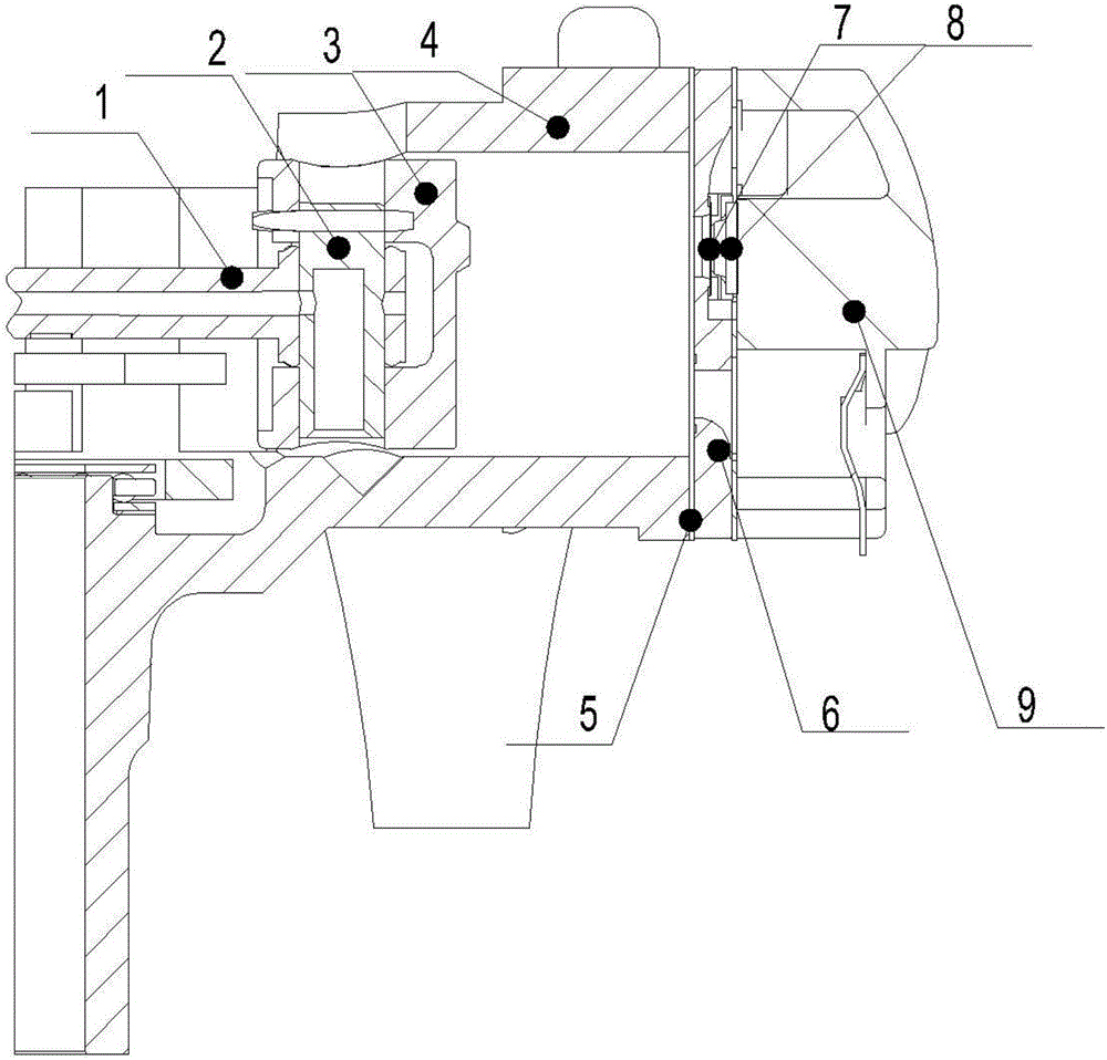
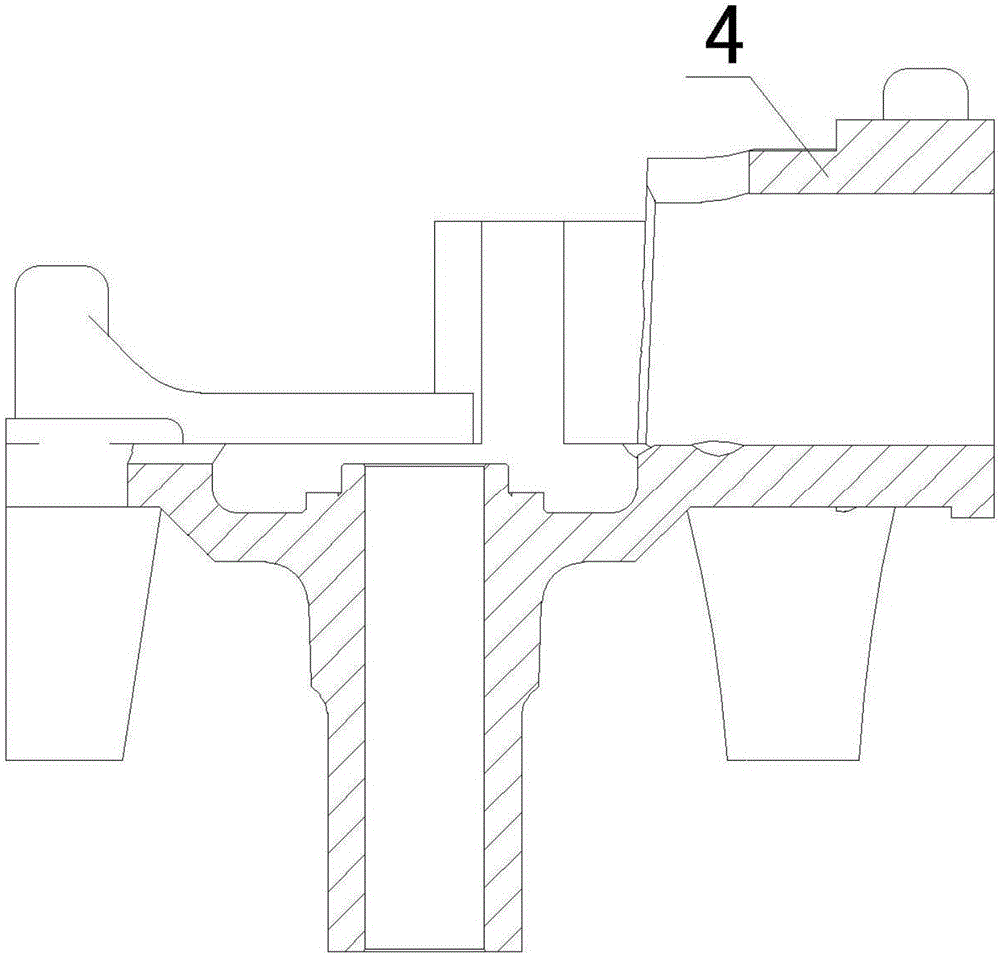
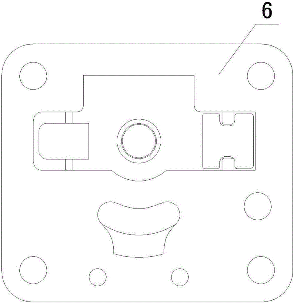
[0016] Such as Figure 4 As shown, the structure of the suction and exhaust system of the present invention includes a connecting rod 1, a piston pin 2, a piston 3, a crankcase 4, a valve plate 6, an exhaust valve plate 7, an exhaust limiter 8 and a cylinder head 9. One end of the connecting rod 1 is connected with the piston 3 through the piston pin 2, the piston 3 is arranged in the crankcase 4, and the exhaust valve plate 7 and the exhaust limiter 8 are arranged on the valve plate 6.

[0017] Please also see Figure 5 Shown, the cylinder hole 13 wall surface of crankcase 4 has offered suction hole 10. The distance a (in mm) between the opening position of the suction hole 10 and the crankcase end surface 12 is greater than 1 / 3 of the piston stroke and less than 1 / 2 of the piston stroke. This distance setting can maximize the cylinder utilization rate of the compressor, and at the same time ensure that the compressor consumes less power during the suction process (if the s...


PUM


Abstract

The invention discloses an air suction and exhaust system structure of a piston type refrigeration compressor. The air suction and exhaust system structure comprises a connection rod, a piston pin, a piston, a crank case, a valve plate, an air exhaust valve sheet, an air exhaust limiter and an air cylinder cover. One end of the connection rod is connected with the piston. The piston is arranged in the crank case. The valve plate is provided with an air exhaust hole. The air exhaust valve sheet and the air exhaust limiter are arranged on the valve plate. The wall face of an air cylinder hole of the crank case is provided with an air suction hole. The distance from the forming position of the air suction hole to the end face of the crank case can be larger than 1/3 of the piston stroke and smaller than 1/2 of the piston stroke. Due to the fact that an air suction valve sheet which is the damageable key part in an existing piston type refrigeration compressor is omitted, the air suction hole is closed and opened through reciprocating motion of the piston so as to achieve the air suction function of the compressor, the cost of the compressor is reduced, the whole compressor noise of the compressor is greatly lowered, the thermodynamic efficiency of the compressor is further improved, and the reliability of the compressor is greatly improved.

Description

technical field [0001] The invention relates to the technical field of refrigeration compressors, in particular to a suction and discharge system structure of a piston refrigeration compressor. Background technique [0002] The working principle of the piston refrigeration compressor is to periodically and alternately realize the supply of refrigerant to the refrigeration system through the suction and exhaust process. Both the suction and exhaust processes are one-way flow of refrigerant. When the piston moves to the bottom dead center, the cylinder volume increases, the gas expands, and the air pressure decreases. When the pressure drops below the suction pressure, the suction valve plate Open, the refrigerant on the low-pressure side enters the cylinder; when the piston moves to the top dead center, the volume of the cylinder decreases, the gas is compressed, and the air pressure increases. When the pressure rises higher than the exhaust pressure, the exhaust valve opens ...

Claims


Application Information

Patent Timeline
Patent Type & Authority Applications(China)
IPC IPC(8): F04B39/00
CPCF04B39/00F04B39/0005F04B39/0027
Inventor 王宗槐武守飞刘小莉李玉茜
Owner JIAXIPERA COMPRESSOR
Why Eureka
Try Eureka