Pneumatic hoist

A hoist and pneumatic technology, which is applied in hoisting devices, clockwork mechanisms, etc., can solve problems such as cumbersome operation and inconvenient use, and achieve the effects of simple operation, ensuring work stability, and eliminating potential safety hazards

Active Publication Date: 2017-04-19
常州市博金机械制造有限公司
View PDF7 Cites 1 Cited by
  • Summary
  • Abstract
  • Description
  • Claims
  • Application Information

AI Technical Summary

Problems solved by technology

[0003] The purpose of the present invention is to overcome the disadvantages of the prior art that the exhaust port and the air intake port need to be interchanged so as to realize the forward and reverse rotation of the air motor, which is cumbersome to operate and inconvenient to use, and provides an air hoist

Method used


Image

  • Pneumatic hoist
  • Pneumatic hoist
  • Pneumatic hoist

Examples


Embodiment 1

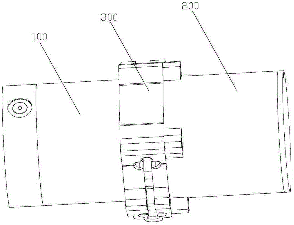
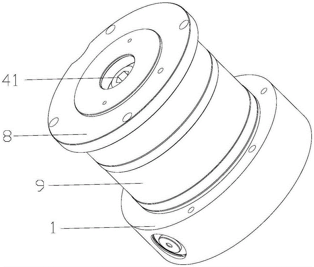
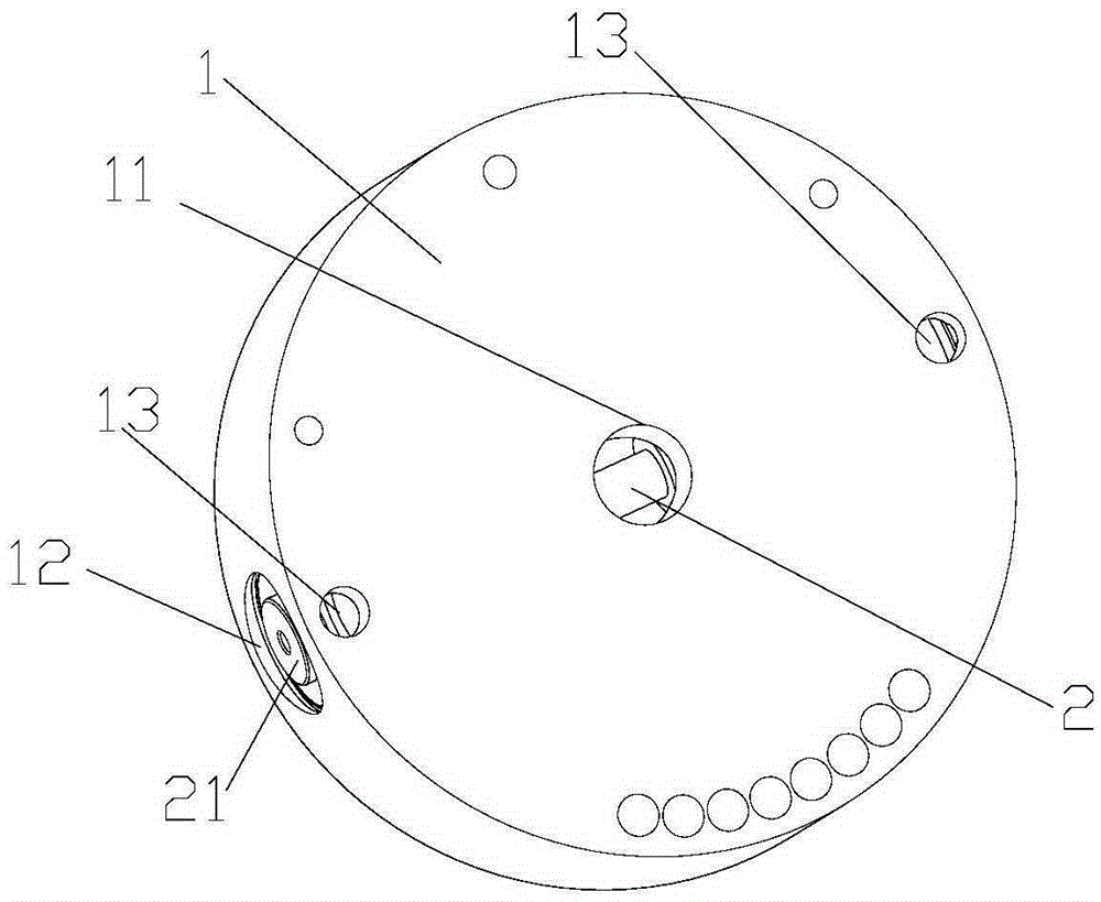
[0038] Such as figure 1 As shown, a pneumatic hoist includes a pneumatic part 100, a transmission part 200 and a lifting part 300; as figure 2 As shown, the pneumatic part 100 includes a vane air motor, a control valve and a braking mechanism.

[0039] The control valve includes a valve sleeve 3, such as Image 6 As shown, the valve sleeve 3 is provided with a first air inlet hole 31 and a first air outlet hole 32 and a second air outlet hole 33 respectively located on both sides of the first air inlet hole 31 .

[0040] Such as Figure 5 with 7As shown, the spool 2, the spool 2 includes two annular protrusions 22 matched with the valve sleeve 3, a first air groove 23 is formed between the two annular protrusions 22, The width of the first air groove 23 is smaller than the distance between the first air outlet 32 ​​and the second air outlet 33; the two ends of the valve core 2 are provided with a piston 24; one end of the piston 24 is provided with a second A spring seat...


PUM


Abstract

The invention belongs to the technical field of hoisting equipment and provides a pneumatic hoist which comprises a pneumatic part, a transmission part and a lifting part. The pneumatic part comprises a blade type pneumatic motor, a control valve and a brake mechanism. The control valve comprises a valve sleeve, a valve element and a valve base, wherein the valve sleeve is provided with a first air inlet hole, a first air outlet hole and a second air outlet hole, and the first air outlet hole and the second air outlet hole are separately located on the two sides of the first air inlet hole; the valve element comprises two annular protrusions which are arranged on the valve element and matched with the valve sleeve, and a first air groove is formed between the two annular protrusions; pistons are arranged at the two ends of the valve element; the valve base is internally provided with a mounting hole, the valve sleeve is fixedly arranged in the mounting hole, and the valve element is slidably arranged in the pistons through the protrusions; the two ends of the mounting hole are closed; and one face of the valve base is provided with two second air inlet holes communicating with the closed end of the mounting hole and a cavity between the pistons, and a power air hole communicating with the first air inlet hole, and the other face of the valve base is further provided with a forward rotating air outlet hole and a backward rotating air outlet hole separately communicating with the first air outlet hole and the second air outlet hole.

Description

technical field [0001] The invention belongs to the technical field of lifting equipment, and in particular relates to a pneumatic hoist. Background technique [0002] The air hoist uses an air motor as the power mechanism and mainly includes three parts, namely the pneumatic part, the transmission part connected with the pneumatic part and the lifting part connected with the transmission part. The vane air motor is a device that converts the pressure energy of compressed air into rotating mechanical energy, mainly including a vane rotor and a stator. If the positive and negative rotation of the air motor is realized, the usual practice in the prior art is that after entering the air chamber from the air inlet, the gas is sprayed to the blade and acts on the protruding part of the blade, generating torque to drive the rotor to rotate forward, and the exhaust gas is discharged from the exhaust port. discharge; while the lowering air inlet and exhaust port are exchanged, that...

Claims


Application Information

Patent Timeline
Patent Type & Authority Applications(China)
IPC IPC(8): B66D1/02B66D1/44
Inventor 李志强
Owner 常州市博金机械制造有限公司
Why Eureka
Try Eureka