An energy-dissipating beam-column joint for building steel structures

A technology of beam-column joints and steel structures, which is applied in the direction of building structures, buildings, building types, etc., can solve the problems of plastic damage of the main structure, occupying a large space, and difficult repairs, so as to reduce economic losses, simple structure, and effective obvious effect

Inactive Publication Date: 2018-01-02
TONGJI UNIV
View PDF5 Cites 2 Cited by
  • Summary
  • Abstract
  • Description
  • Claims
  • Application Information

AI Technical Summary

Problems solved by technology

However, due to the plastic damage area of ​​the main structure in this way, it will bring great difficulties to the repair after the earthquake, and at the same time, the repair of this structure after the earthquake will bring huge economic losses
The other is to dissipate the seismic energy by setting additional energy-dissipating and shock-absorbing devices. The common ones are metal dampers, viscous dampers, and tuned mass dampers. Although this method can overcome the shortcomings of the first method, the This method will take up a lot of space and may affect architectural requirements

Method used


Image

  • An energy-dissipating beam-column joint for building steel structures
  • An energy-dissipating beam-column joint for building steel structures
  • An energy-dissipating beam-column joint for building steel structures

Examples


Embodiment 1

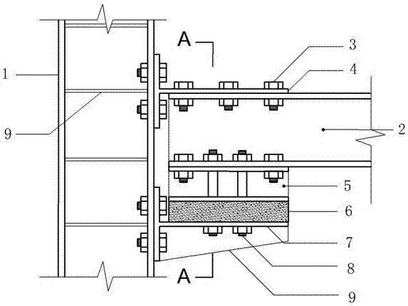
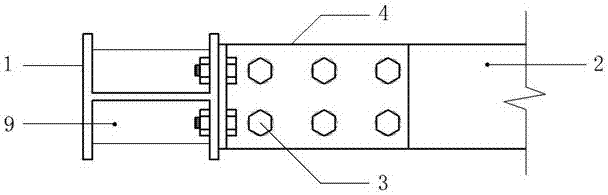
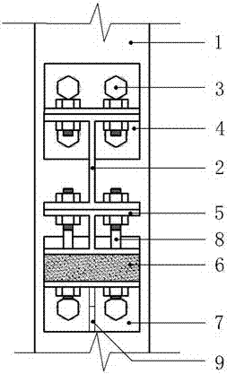
[0022] Embodiment 1: as Figure 1~4 As shown, it is an embodiment of an energy-dissipating beam-column node for building steel structures according to the present invention, including frame columns 1, frame beams 2, high-strength bolts 3, upper T-shaped connectors 4, small I-shaped steel connectors 5, Viscous friction damper 6, lower T-shaped connector 7, metal energy-dissipating rod 8, stiffener 9, in which two T-shaped connectors 4 and 7 are placed horizontally (the vertical web of the flange is horizontal); viscous The friction damper 6 has multiple layers, and dissipates energy through relative movement between layers; both ends of the metal energy dissipation rod 8 are threaded, and nuts can be screwed. Specific connection: the flange and web of the upper T-shaped connector 4 are respectively connected to the flange of the frame column 1 and the upper flange of the frame beam 2 through high-strength bolts 3, and at the same time, the lower flange of the frame beam 2 is al...


PUM


Abstract

The invention relates to an energy dissipation beam column joint for a building steel structure. The energy dissipation beam column joint comprises a frame beam column, T-shaped connection parts, a viscous friction damper, a small I-shaped steel connection part, a metal energy dissipation bar and the like. Connection of the beam end comprises the upper T-shaped connection part, a frame beam, the small I-shaped steel connection part, the viscous friction damper and the lower T-shaped connection part. Except that the viscous friction damper and the small I-shaped steel connection part as well as the lower T-shaped connection part are bonded through strong glue, the others are all connected through high-strength bolts. The upper T-shaped connection part and the lower T-shaped connection part are connected with the frame beam through high-strength bolts. The whole metal energy dissipation bar penetrates through the lower flange of the frame beam to the lower T-shaped connection part and is fixed through a nut. When horizontal seismic force is small, the viscous friction damper can provide certain lateral resisting stiffness. When horizontal seismic force is large, relative sliding occurs to all layers of the viscous friction damper, the metal energy dissipation bar is driven to be subjected to bending deformation, joint energy dissipation is achieved, and a mixed energy dissipation system is formed. The energy dissipation beam column joint is simple in structure, significant in energy dissipation and seismic mitigation effect and suitable for various connection positions and does not occupy additional space.

Description

technical field [0001] The invention belongs to the anti-seismic field of building steel structures, and in particular relates to an energy-dissipating beam-column node for building steel structures. Background technique [0002] In recent years, passive control technology in earthquake protection engineering has been widely used in civil engineering at home and abroad because of its low cost and significant shock absorption effect, among which energy dissipation and shock absorption technology is the most common. There are two main methods of energy dissipation and shock absorption: one is to dissipate energy through the deformation of the structural members themselves, that is, to weaken the flexural bearing capacity of some beam areas, so that plastic energy dissipation occurs first in this area, and the purpose of energy dissipation and shock absorption is achieved. However, due to the plastic damage area of ​​the main structure in this way, it will bring great difficult...

Claims


Application Information

Patent Timeline
Patent Type & Authority Patents(China)
IPC IPC(8): E04B1/24E04H9/02
CPCE04B1/2403E04B2001/2406E04H9/024
Inventor 鲁正张恒锐廖元
Owner TONGJI UNIV
Why Eureka
Try Eureka