Convenient electronic lock

An electronic lock, a convenient technology, applied in the field of electronic locks, can solve the problems of inability to successfully unlock the lock at one time, large movement resistance of the sliding block, and large overall volume of the electronic lock, and achieve high mechanical energy transmission efficiency, low power consumption requirements, and increased convenience. Effect

Active Publication Date: 2017-04-19
DONGGUAN XIAODUN INTELLIGENT TECH CO LTD
View PDF5 Cites 5 Cited by
  • Summary
  • Abstract
  • Description
  • Claims
  • Application Information

AI Technical Summary

Problems solved by technology

[0003] The electronic locks of the prior art have the following deficiencies: 1. Each part of the mechanical linkage requires a relatively large force to realize the linkage, so the motor power is large; 2. One side of the cam is provided with a round groove for locking. When the push rod is in contact with the sliding block, the movement resistance of the sliding block is large, and the motor needs to provide a greater force to unlock, and it is often impossible to unlock successfully at one time, which is inconvenient to use. 3. When the external force is applied, the sliding block will be in the Sliding along the sliding rod under the action of external force, resulting in the disconnection of the push rod and the sliding block, the push rod loses the force of the sliding block and then moves back, and the electronic lock is opened, so the safety performance is not high
4. The motor consumes a lot of power and requires a lot of power. The overall volume of the electronic lock is large and the battery life is short.
5. Inconvenient installation and inconvenient use

Method used


Image

  • Convenient electronic lock
  • Convenient electronic lock
  • Convenient electronic lock

Examples


Embodiment Construction

[0040] The present invention will be further described below in conjunction with the accompanying drawings.

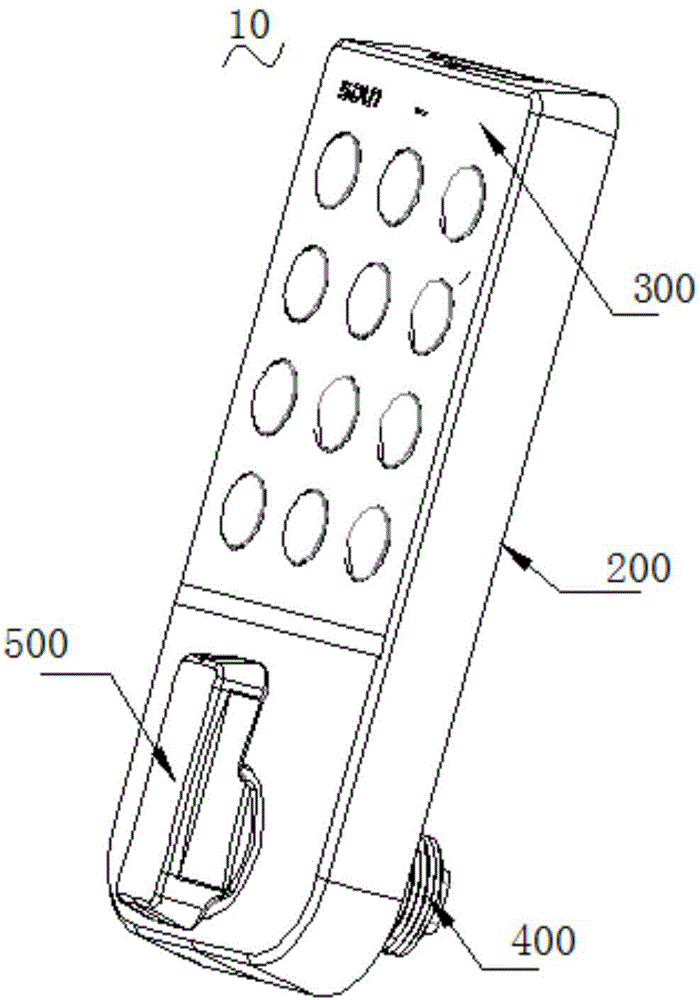
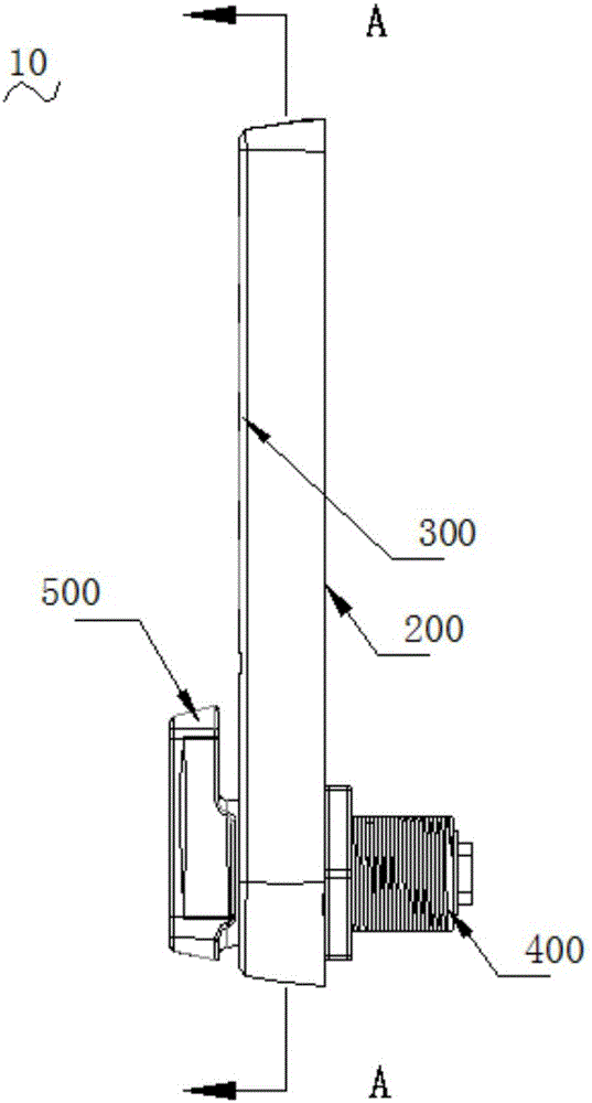
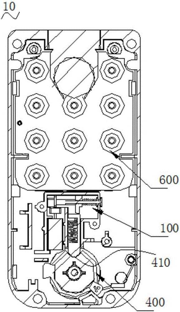
[0041] like Figure 1 ~ Figure 3 Shown are the perspective view, side view and A-A sectional view of the electronic lock of the specific embodiment 1 respectively.

[0042] The electronic lock 10 with the control mechanism 600 includes a bottom plate 200, a lock case 300 surrounding one side of the bottom plate 200, a lock cylinder installed on the lock case 300 and extending into the space formed by the lock case 300 and the bottom plate 200 400, the knob 500 installed on the side of the lock case 300 away from the lock cylinder 400 and connected to the lock cylinder 400, the transmission mechanism 100 installed in the space enclosed by the lock case 300 and the bottom plate 200 and connected to the lock cylinder 400, used The control mechanism 600 for controlling the movement of the transmission mechanism 100 to realize locking and unlocking also includes an install...


PUM


Abstract

The invention relates to the field of electronic locks, in particular to a convenient electronic lock. The convenient electronic lock comprises a base plate, a lock shell arranged on one side of the base plate in a surrounding manner, a lock cylinder installed on the lock shell, a rotary knob installed on the side, away from the lock cylinder, of the lock shell and connected with the lock cylinder, a transmission mechanism installed in space defined by the lock shell and the base plate, a control mechanism connected to the transmission mechanism to control the transmission mechanism to move and an installation mechanism used for installing the electronic lock to an to-be-installed part; and one end of the lock cylinder extends into the space defined by the lock shell and the base plate. The convenient electronic lock is low in power dissipation, high in safety and convenient and rapid to use.

Description

technical field [0001] The invention relates to the field of electronic locks, in particular to a convenient electronic lock. Background technique [0002] After a long development of locks, with the advancement of modern electronic science and technology, this antique with a history of thousands of years has finally entered the lives of modern people on the sailboat of new technology, carrying the utility of traditional locks and the use of modern electronics. The emergence of electronic locks has made more and more modern people feel the power of technology. Compared with traditional locks, electronic locks have more advantages. First, there is no need to prepare mechanical keys, and the lock can be unlocked by password, scanning QR code, Scanning the user's biometric feature to unlock the lock will not cause the lock to be unopened due to the loss of the key. Second, the electronic lock controls the control mechanism through the circuit, which has high security. [0003]...

Claims


Application Information

Patent Timeline
Patent Type & Authority Applications(China)
IPC IPC(8): E05B47/00E05B49/00E05B15/00
CPCE05B15/00E05B47/0012E05B49/00E05B2047/0018
Inventor 任剑波
Owner DONGGUAN XIAODUN INTELLIGENT TECH CO LTD
Why Eureka
Try Eureka