Efficient waste heat utilization system for coal-to-liquids technology condensate

A technology for process condensate and coal-to-oil, which is applied in the field of coal-to-oil to achieve the effects of obvious energy saving and emission reduction, wide application prospects and improved comprehensive utilization efficiency

Inactive Publication Date: 2017-04-19
SICHUAN XINMA ENERGY TECH CO LTD
View PDF7 Cites 4 Cited by
  • Summary
  • Abstract
  • Description
  • Claims
  • Application Information

AI Technical Summary

Problems solved by technology

[0004] In order to solve the defects of the condensate cooling method in the existing coal-to-liquid (coal liquefaction) process, the present invention provides a high-efficiency utilization system of condensate waste heat in the coal-to-liquid process to improve the comprehensive utilization efficiency of energy

Method used


Image

  • Efficient waste heat utilization system for coal-to-liquids technology condensate
  • Efficient waste heat utilization system for coal-to-liquids technology condensate
  • Efficient waste heat utilization system for coal-to-liquids technology condensate

Examples


Embodiment 1

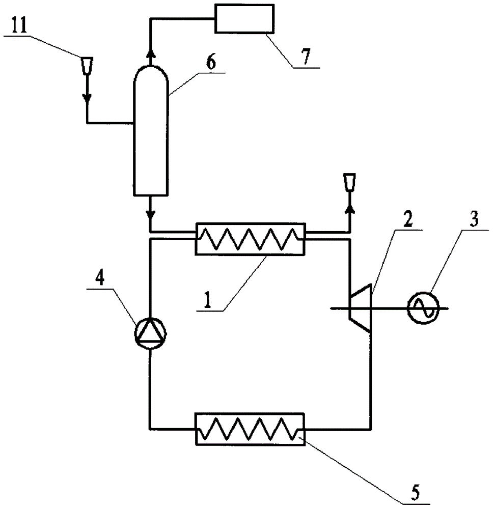
[0018] see figure 2 , the present invention discloses a high-efficiency utilization system for condensate waste heat in coal-to-liquids process. The system includes a two-stage waste heat utilization system. The first-stage waste heat utilization system adopts a flash heat recovery system to recover flash steam, and the second-stage waste heat utilization system The system uses the Organic Rankine Cycle (ORC cycle) to generate electricity.

[0019] The first-stage waste heat utilization system is a flash heat recovery system, including a flash tank 6 and a steam heat recovery device 7, and the high-temperature process condensate (usually at a temperature of 110-130°C) is connected to the flash tank through the process condensate interface 11 Inlet 6, saturated steam is flashed out, and the flash steam is connected to the steam heat recovery device 7 from the top of the flash tank 6 for use in other processes, and the low-temperature condensate at the outlet of the flash heat ...

Embodiment 2

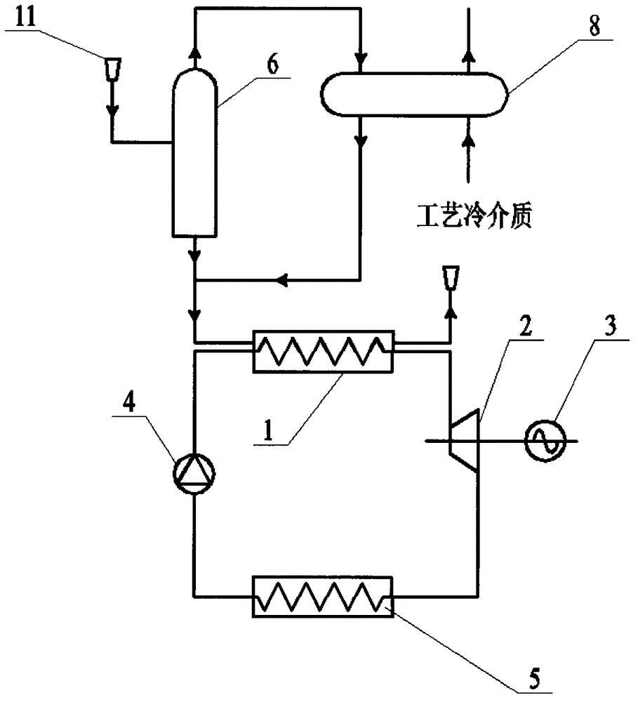
[0022] see image 3 , The difference between Embodiment 2 and Embodiment 1 is that in this embodiment, the steam heat recovery and utilization device of the first-stage waste heat utilization system is a steam condenser 8, and the high-temperature process condensate (usually at a temperature of 110-130° C.) passes through the process The condensate interface 11 is connected to the inlet of the flash tank 6, and saturated steam is flashed out. The flash steam enters the steam condenser 8 from the top of the flash tank 6 to condense and release heat, which is used for heating the process cold medium. After the condensate is mixed with the condensate at the outlet of the flash tank (at a temperature of 75°C to 100°C), it enters the second-stage waste heat utilization system.

Embodiment 3

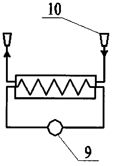
[0024] see Figure 4 The difference between Embodiment 3 and Embodiment 1 is that in this embodiment, the steam heat recovery and utilization device of the first-stage waste heat utilization system is a steam jet heat pump 9, and the high-temperature process condensate (usually at a temperature of 110-130°C) passes through the process The condensate interface 11 is connected to the inlet of the flash tank 6 to flash saturated steam. The flash steam enters the steam injection heat pump 9 from the top of the flash tank 6 and mixes with the high-temperature and high-pressure driving steam to form usable steam. The flash tank 6. The low-temperature condensate (with a temperature of 75°C to 100°C) at the outlet enters the second-stage waste heat utilization system.


PUM


Abstract

An efficient waste heat utilization system for coal-to-liquids technology condensate comprises two stages of waste heat utilization systems. The first-stage waste heat utilization system is a flash heat recycling system and comprises a flash tank and a steam heat recycling device. High-temperature condensate is fed into an inlet of the flash tank. Saturated steam is flashed out and fed into the steam heat recycling device for other technologies. Low-temperature condensate of an outlet of the flash heat recycling system is fed into the second-stage waste heat utilization system. The second-stage waste heat utilization system is an organic Ranking cycle system (ORC) and comprises an evaporator, an expander, a generator, a working medium pump and a condenser. The low-temperature condensate of the outlet of the flash heat recycling system is fed into the evaporator of the second-stage waste heat utilization system and drives the generator of the ORC to generate electricity. The efficient waste heat utilization system for the coal-to-liquids technology condensate achieves conversion of the condensate cooling manner to an energy generation type from an energy consumption type, the comprehensive utilization efficiency of condensate energy is greatly improved, and the energy conservation and emission reduction effects are remarkable.

Description

technical field [0001] The invention relates to the field of coal-to-oil technology, in particular to a system for efficiently utilizing condensate waste heat in the coal-to-oil process. Background technique [0002] In the coal-to-oil (coal liquefaction) process, high-temperature process condensate (usually at a temperature of 110°C to 130°C) will be produced, and these process condensate must be cooled to a certain temperature (usually at a temperature of 50°C to 75°C) To enter the process condensate tank. The current process is to use water-cooled cooling tower for cooling treatment (see attached figure 1 ), the heat released by the cooling of the process condensate is discharged to the atmosphere through the cooling water. This method not only does not effectively utilize the heat energy of the process condensate, but also consumes additional electric energy in the cooling tower circulation system, which belongs to energy-consuming cooling. [0003] In view of this, i...

Claims


Application Information

Patent Timeline
Patent Type & Authority Applications(China)
IPC IPC(8): F01K27/02F01K25/08F22B1/16
Inventor 马永杰徐峰
Owner SICHUAN XINMA ENERGY TECH CO LTD
Why Eureka
Try Eureka