Ultrasonic phased array inspection method for U-rib bilateral fillet weld
An ultrasonic phased array and detection method technology, which is applied to the analysis of solids using sound waves/ultrasonic waves/infrasonic waves, material analysis using sound waves/ultrasonic waves/infrasonic waves, and measuring devices. It can solve the problems of low precision, low work efficiency, and quantitative accuracy. Poor and other problems, to achieve the effect of ensuring welding quality, strong practicability, and intuitive readings
- Summary
- Abstract
- Description
- Claims
- Application Information
AI Technical Summary
Problems solved by technology
Method used
Image
Examples
Embodiment 1
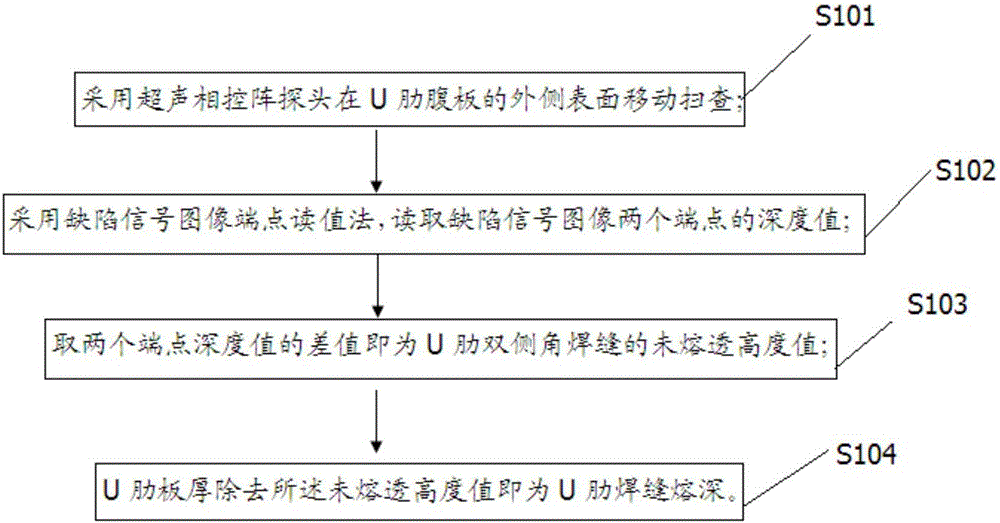
[0044] Such as figure 1 As shown, Embodiment 1 of the present invention uses the ultrasonic phased array detection method to detect the penetration depth of U-rib bilateral fillet welds, including the following steps:
[0045] S101: Use an ultrasonic phased array probe to move and scan the outer surface of the U-rib web;
[0046] S102: Using the defect signal image endpoint reading method to read the depth values of the two endpoints of the defect signal image;
[0047] S103: The difference between the depth values of the two endpoints is taken as the non-penetration height value of the U rib bilateral fillet weld;
[0048] S104: The thickness of the U-rib plate minus the value of the unpenetrated height is the U-rib weld penetration.
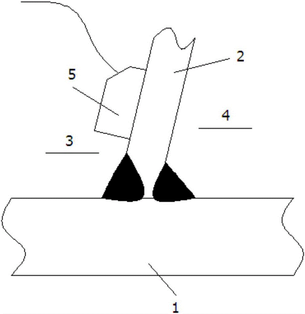
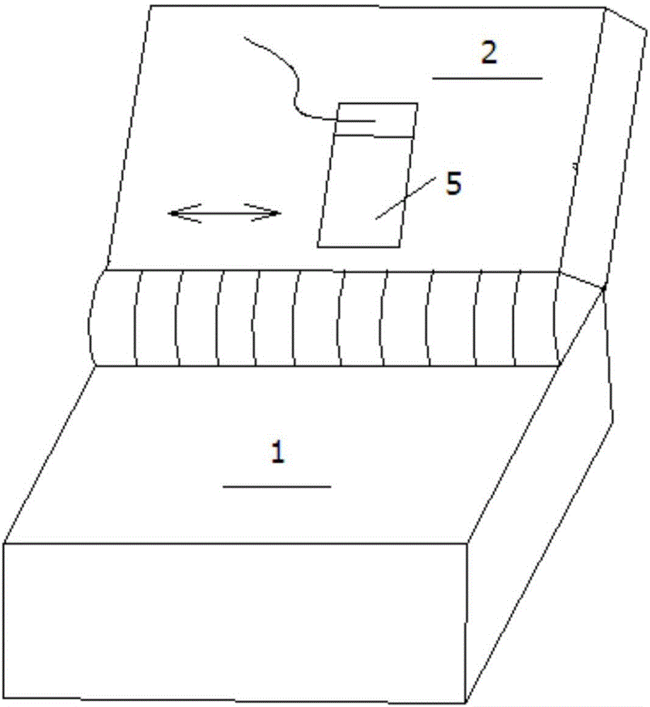
[0049] figure 2 It is a schematic diagram of the use state of using the ultrasonic phased array detection method to detect the penetration depth of U-rib bilateral fillet welds in Embodiment 1 of the present invention. Such as image ...
Embodiment 2
[0055] Embodiment 2 of the present invention uses an ultrasonic phased array detection method to detect the penetration depth of U-rib bilateral fillet welds, including the following steps:
[0056] S201: Use an ultrasonic phased array probe to move and scan the outer surface of the U-rib web;
[0057] S202: Using the defect signal image endpoint reading method to read the depth values of the two endpoints of the defect signal image;
[0058] S203: the difference between the depth values of the two endpoints is taken as the non-penetration height value of the U rib bilateral fillet weld;
[0059] S204: The thickness of the U rib plate minus the value of the unpenetrated height is the penetration depth of the U rib weld.
[0060] The frequency of the phased array probe is 5MHZ, the number of chips is 32, and the chip spacing is 0.31mm.
[0061] The phased array probe moves on the outer surface of the U-rib web along the direction of the U-rib outer fillet weld bead.
Embodiment 3
[0063] Embodiment 3 of the present invention uses the ultrasonic phased array detection method to detect the transverse crack of the U-rib bilateral fillet weld comprising the following steps:
[0064] The ultrasonic phased array probe is used to scan the surface of the fillet weld to detect transverse cracks, that is, the probe rides on the surface of the outer weld bead of the U rib to move back and forth. However, the phased array flaw detection itself still emits ultrasonic beams from multiple angles for weld detection.
[0065] The frequency of the phased array probe is 5MHZ, the number of chips is 16, the chip spacing is 0.4mm, and the wedge width is 10mm.
[0066] The model of the GE ultrasonic phased array equipment is PHOSOR XS.
[0067] Figure 5 It is a schematic diagram of the use state of using the ultrasonic phased array detection method to detect the transverse cracks of the U-rib bilateral fillet welds in Embodiment 3 of the present invention. Such as Imag...
PUM
 Abstract
Description
Claims
Application Information
 - R&D
- Intellectual Property
- Life Sciences
- Materials
- Tech Scout
- Unparalleled Data Quality
- Higher Quality Content
- 60% Fewer Hallucinations
Browse by: Latest US Patents, China's latest patents, Technical Efficacy Thesaurus, Application Domain, Technology Topic, Popular Technical Reports.
© 2025 PatSnap. All rights reserved.Legal|Privacy policy|Modern Slavery Act Transparency Statement|Sitemap|About US| Contact US: help@patsnap.com


