DMD component, DLP light machine and DLP projection device

A component and host technology, applied in the field of optics and projection, can solve problems such as difficulty in ensuring fixed precision, low contact stability, and non-relative fixation, so as to improve production efficiency and product quality, improve accuracy and stability, The effect of ensuring accuracy and stability

Active Publication Date: 2017-04-19
QINGDAO HISENSE LASER DISPLAY CO LTD
View PDF17 Cites 16 Cited by
  • Summary
  • Abstract
  • Description
  • Claims
  • Application Information

AI Technical Summary

Problems solved by technology

[0007] 1. Due to the one-to-one correspondence between the multiple contacts of the driver board and the DMD chip, it is difficult to ensure the fixing accuracy in this way, and there are cases where the contacts are not corresponded to each other, and the requirements for the size and installation methods of related structural parts are relatively high;
[0008] 2. The multiple contacts of the driver board and the DMD chip need to be tightly attached to each other, but because the flatness of the DMD chip itself is difficult to guarantee, using this method of fixing may lead to uneven force and poor contact of local contacts, and due to The back-end heat sink is large in size and weight. There is only a gap between the protruding heat sink and the back of the DMD chip to fill w

Method used


Image

  • DMD component, DLP light machine and DLP projection device
  • DMD component, DLP light machine and DLP projection device
  • DMD component, DLP light machine and DLP projection device

Examples


Embodiment Construction

[0049] The present invention is further described below with reference to the accompanying drawings and exemplary embodiments, wherein like numerals in the drawings refer to like parts throughout. Also, if a detailed description of known art is not necessary to illustrate the features of the present invention, it will be omitted.

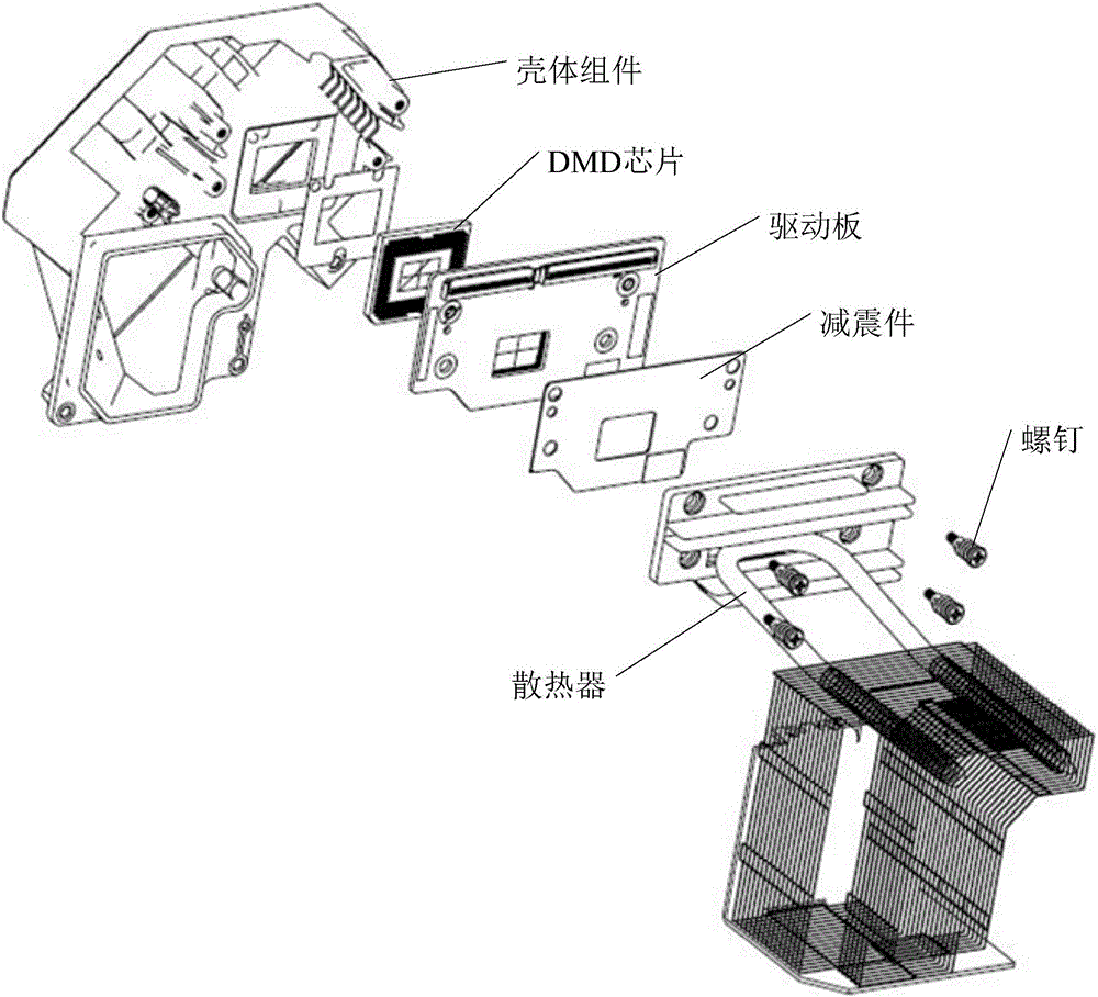
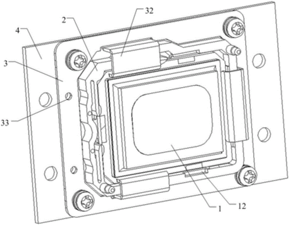
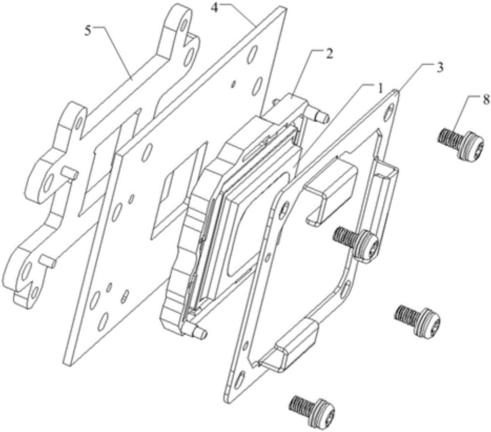
[0050] The schematic structural diagrams of a typical embodiment of a DMD assembly provided by the present invention are shown in 2 to 10. The DMD assembly includes a DMD fixing structure and a DMD chip 1 and a driving board 4 arranged on the DMD fixing structure, wherein, The DMD assembly includes a base 2 for mounting the DMD chip 1 , a support plate 5 and a fixing frame 3 for fixing the driving board 4 .

[0051] Wherein, the base 2 is provided with a mounting groove 22 for the embedded installation of the DMD chip 1 , and the mounting groove 22 has an elastic limiting structure 23 for mounting and fixing the DMD chip 1 installed therein. The st...


PUM


Abstract

The invention relates to the technical field of optics and projection, and particularly relates to a DMD component, a DLP light machine and a DLP projection device. The DMD component comprises a base with an accommodation groove on one side, a driving plate, a DMD chip which is arranged in the accommodation groove, a supporting plate and a fixation frame with an embedded through hole. A number of elastic hooks are arranged on the edge of one side of the embedded through hole. The driving plate is fixedly clamped between the fixation frame and the supporting plate through a fastener. The base is embedded into the embedded through hole from one side, which is close to the driving plate, of the fixation frame, and the elastic hooks on the other side hook the edge of the inner wall of the accommodation groove and contact the surface of the DMD chip. According to the invention, the accuracy and stability of the contact between the DMD chip and the contact of the driving plate are ensured; the quality of the final projection screen is improved; the difficulty of disassembly and assembly and the requirement on the size of associated structural members are reduced; the efficiency of processing and production is improved; and the production cost is reduced.

Description

[0001] 【Technical field】 [0002] The present invention relates to the technical field of optics and projection, in particular to a DMD component, a DLP optical machine and a DLP projection device. [0003] 【Background technique】 [0004] DLP (Digital Light Procession, digital light processing) projectors have the characteristics of high native contrast, miniaturization of machines, and closed optical paths, which make them more and more favored by users. Among them, DLP projectors use DMD ( Digtal Micromirror Device (Digital Micromirror Device) chip is used as an imaging device to realize a projection technology of projected images by adjusting the reflected light. [0005] In the prior art, the connection between the DMD and the drive board is a multi-contact connection; please refer to the appendix. figure 1 , The traditional contact between the DMD chip and the driver board is mainly achieved by locking the driver board with screws, and then the driver board presses the co...

Claims


Application Information

Patent Timeline
IPC IPC(8): G03B21/00G03B21/14G03B21/16
CPCG03B21/008G03B21/14G03B21/16
Inventor 侯乃文
Owner QINGDAO HISENSE LASER DISPLAY CO LTD
Why Eureka
Try Eureka