Regeneration electromotive force discharge device for DC drive

A discharge device and DC drive technology, applied in the direction of emergency protection circuit device, circuit device, emergency protection circuit device, etc. for limiting overcurrent/overvoltage, can solve the problem of overvoltage protection of switching power supply, system malfunction, Problems such as power-off and restart of the chip can achieve the effects of low on-resistance, saving assembly space, and reducing hardware costs

Active Publication Date: 2017-04-19
SHANGHAI ANPU MINGZHI AUTOMATION EQUIP
View PDF5 Cites 5 Cited by
  • Summary
  • Abstract
  • Description
  • Claims
  • Application Information

AI Technical Summary

Problems solved by technology

After the output voltage of the power supply is raised by the regenerative electromotive force, it is very easy to cause overvoltage protection of the switching power supply, or the internal drive chip of the power supply is powered off and restarted, or the power supply is directly damaged, causing the system to fail to operate normally.

Method used


Image

  • Regeneration electromotive force discharge device for DC drive
  • Regeneration electromotive force discharge device for DC drive
  • Regeneration electromotive force discharge device for DC drive

Examples


Embodiment

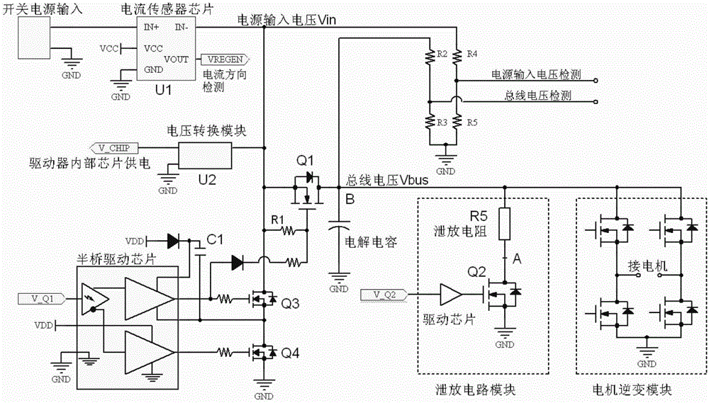
[0038] Such as figure 1 As shown, the present invention can be used for the regenerative electromotive force discharge device of the DC drive. By adding a simple discharge circuit inside the DC drive and then matching it with DSP control, the effective discharge of the regenerative electromotive force of the DC drive can be realized, and the normal operation of the power supply can be ensured. Work.

[0039] The hardware principle is explained here:

[0040] Through the current sensor chip monitoring the current flow in and out on the bus, the DSP compares its output voltage with the reference voltage to obtain the current flow state, thereby controlling the on and off of the MOS tube on the bus to cut off the regenerative electromotive force return to the switching power supply. After the internal bus voltage of the driver is raised, the MOS tube of the discharge circuit is turned on, and the regenerative electric energy is discharged. The whole process will not affect the...

Embodiment approach

[0048] The DC drive regenerative electromotive force discharge method mentioned in the present invention is divided into 2 actions: controlling the MOS tube Q1 on the bus and controlling the discharge circuit MOS tube Q2, such as figure 1 shown.

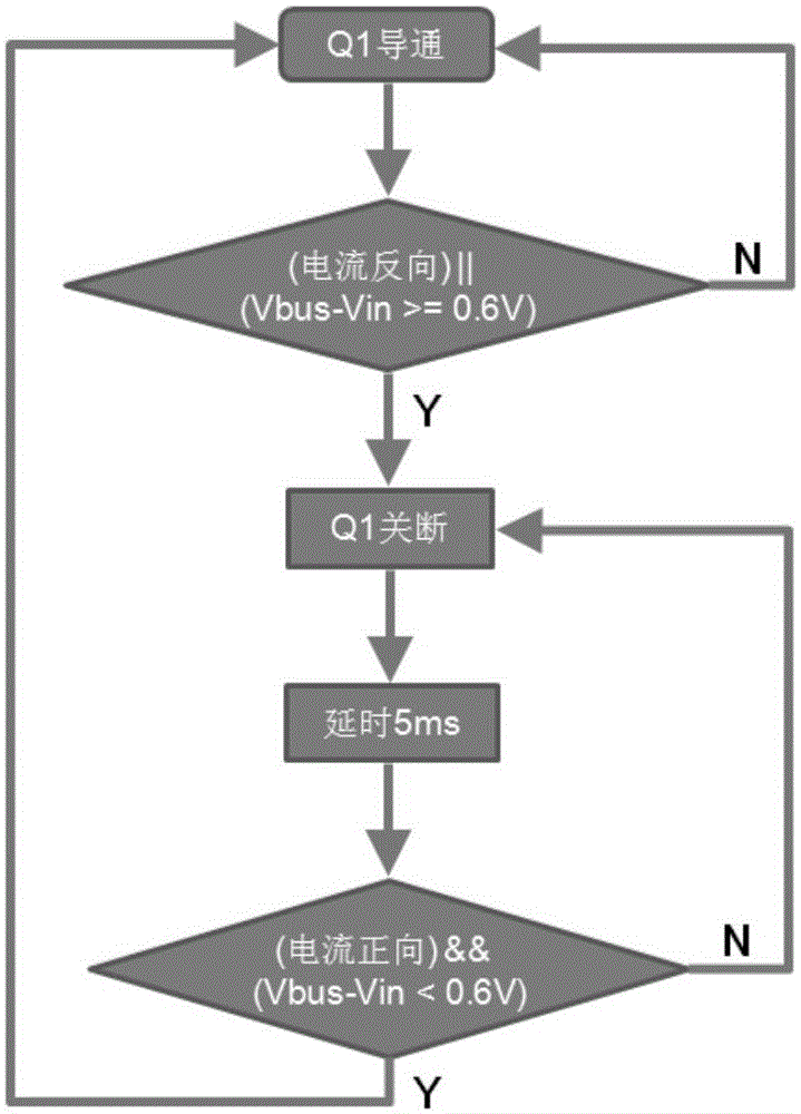
[0049] 1. In the case of no need to discharge normally, the bus MOS tube Q1 is turned on, and the MOS tube Q2 of the bleeder circuit is turned off;

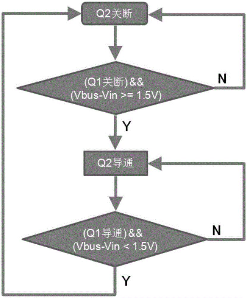
[0050] 2. The operation after the regenerative electromotive force is detected is: first turn off the bus MOS transistor Q1, and then turn on the discharge circuit MOS transistor Q2 to discharge the energy.

[0051] The turn-off conditions of the bus MOS tube are two:

[0052] (1) There is a reverse current;

[0053] (2), the bus voltage is higher than the power input voltage by a certain difference (for example, the difference is set to 0.6V);

[0054]As long as one of the conditions (1) and (2) is met, the bus MOS transistor Q1 is set to be turned off. In order to avoid the high-f...


PUM


Abstract

The invention relates to a regeneration electromotive force discharge device for DC drive, and the device comprises a current sensor which is directly connected to a DC bus, and is used for monitoring the incoming and outgoing of a current on the bus; a bus MOS tube which is connected to the DC bus, and is used for cutting a regeneration electromotive force and returning the regeneration electromotive force to a switching power supply; a discharge current module which is connected to the DC bus and is used for discharging the regeneration electromotive force; and a DSP which is connected with the current sensor, the bus MOS tube and the discharge current module, collects a signal of the current sensor, compares the output voltage of the signal with a reference voltage, and then obtains the flowing state of the current, thereby controlling the on/off of the bus MOS tube. Compared with the prior art, the device is simple and feasible, and can effectively solve a problem that the poor discharge of DC drive causes the power failure.

Description

technical field [0001] The invention relates to a direct current drive, in particular to a regenerative electromotive force discharge device for direct current drive. Background technique [0002] In the four-quadrant motor drive system, the discharge of the regenerative electromotive force has always been a must-have function of the driver in the case of high acceleration and deceleration. [0003] At present, in the AC drive, the regenerative electromotive force discharge technology is relatively mature, mainly through real-time detection of the bus voltage, and when the bus voltage is detected to reach the starting point of discharge, the discharge circuit is opened to discharge the regenerative electromotive force, usually through the consumption Dissipating resistance to complete the release of regenerative energy; when it is detected that the bus voltage is lower than the discharge stop point, the discharge circuit is closed to discharge the regenerative electromotive ...

Claims


Application Information

Patent Timeline
Patent Type & Authority Applications(China)
IPC IPC(8): H02H9/04
Inventor 张圆圆周复
Owner SHANGHAI ANPU MINGZHI AUTOMATION EQUIP
Why Eureka
Try Eureka