Overvoltage detection circuit

A detection circuit, overvoltage and undervoltage technology, applied in the direction of measuring electrical variables, measuring devices, measuring current/voltage, etc., can solve problems such as circuit noise interference and system instability, and achieve the effect of improving response speed

Active Publication Date: 2017-04-19
深圳市一生微电子有限公司
View PDF3 Cites 13 Cited by
  • Summary
  • Abstract
  • Description
  • Claims
  • Application Information

AI Technical Summary

Problems solved by technology

[0004] Although the existing overvoltage and undervoltage circuits can protect the main control chip by controlling the switch detection module in both overvoltage and undervoltage conditions, the circuit is susceptible to noise interference and is frequently turned on or off at the overvoltage and undervoltage detection points. broken modules, and eventually cause system instability;

Method used


Image

  • Overvoltage detection circuit
  • Overvoltage detection circuit
  • Overvoltage detection circuit

Examples


Embodiment approach

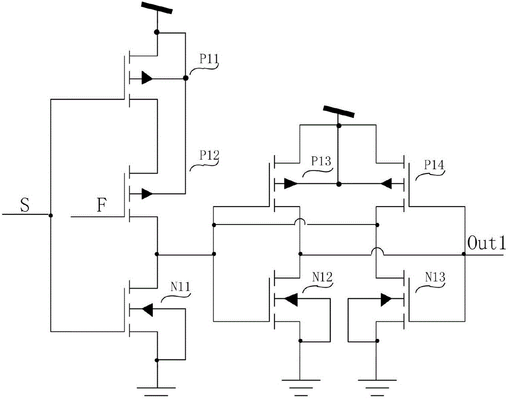
[0093] The SF latch is set through the S terminal, that is, when S=1 and F=0, regardless of the state of the initial state Out1, the secondary state Out1*=1;

[0094] The SF latch is set through the S terminal, that is, when S=1, F=1, regardless of the state of the initial state Out1, the secondary state Out1*=1;

[0095] The SF latch is reset through the S terminal and the F terminal, that is, when S=0, F=0, no matter what state the initial state Out1 is, the secondary state Out1*=0;

[0096] The SF latch follows through the F terminal, that is, when S=0, F=1, no matter what state the initial state Out1 is, the secondary state Out1*=Out1;

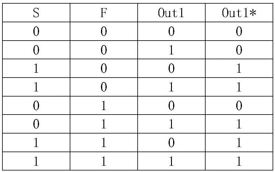
[0097] In summary, there are differences between the SF latch and the traditional RS latch in the working mode. image 3 List the output Out1* corresponding to various current input situations;

[0098] They are all set through the S terminal, but when the RS latch is set, R=0, while the SF latch has nothing to do with the state of F;

...


PUM


Abstract

The present invention discloses an overvoltage detection circuit. The overvoltage detection circuit comprises an overvoltage reference voltage source, an undervoltage reference voltage source, a power source voltage acquisition module, a logic circuit module, an overvoltage and undervoltage comparison module and a latch module; the logic circuit module comprises a two-input OR gate logic circuit OR1 and a two-input OR gate logic circuit OR2; the overvoltage and undervoltage comparison module comprises an overvoltage comparison module and an undervoltage comparison module; the overvoltage detection circuit integrates an overvoltage circuit and an undervoltage circuit; and an overvoltage point and an undervoltage point both have two threshold voltages, so that it can be ensured that the overvoltage detection circuit can operate stably in the vicinities of an overvoltage threshold point and an undervoltage threshold point. In addition, the overvoltage detection circuit of the present invention is different from an existing mainstream technology according to which hysteresis is realized through feedback, therefore, the response speed of the overvoltage detection circuit is greatly improved.

Description

technical field [0001] The invention relates to a protection circuit based on CMOS integrated circuit technology, in particular to an overvoltage and undervoltage detection circuit for CMOS integrated circuit overvoltage and undervoltage detection. Background technique [0002] CMOS integrated circuits are realized by connecting single or multiple functions that are expected to be realized by connecting various devices manufactured on wafers into circuits. CMOS integrated circuits have specific operating voltage ranges for their own devices. If the given voltage exceeds these The maximum rating of the device often causes irreversible damage to the chip; [0003] In order to prevent the chip from being damaged or the peripheral circuit from being damaged due to abnormal operation of the chip, it is usually necessary to set a corresponding safe working voltage range. If the given voltage is too high or too low, the chip can be protected by its own circuit. [0004] Although t...

Claims


Application Information

Patent Timeline
Patent Type & Authority Applications(China)
IPC IPC(8): H03K19/003G01R19/165
CPCG01R19/16557H03K19/00315
Inventor 何邦君王冠军叶东
Owner 深圳市一生微电子有限公司
Why Eureka
Try Eureka