Turbo refrigeration machine

A turbo refrigerator and refrigerant technology, applied in refrigerators, refrigeration components, refrigeration and liquefaction, etc., can solve problems such as low density, and achieve the effect of ensuring flow, efficient operation, and stable operation

Active Publication Date: 2017-04-19
MITSUBISHI HEAVY IND THERMAL SYST
View PDF5 Cites 2 Cited by
  • Summary
  • Abstract
  • Description
  • Claims
  • Application Information

AI Technical Summary

Problems solved by technology

It is known that the R1233zd(E) refrigerant is a low-pressure refrigerant with low density

Method used


Image

  • Turbo refrigeration machine
  • Turbo refrigeration machine
  • Turbo refrigeration machine

Examples


no. 1 Embodiment approach

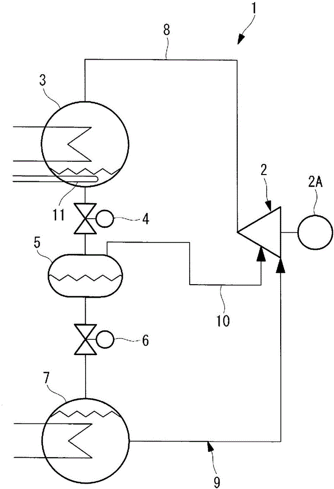
[0029] Below, use figure 1 and figure 2 A first embodiment of the present invention will be described.

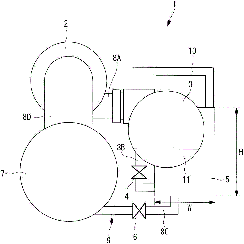
[0030] figure 1 A refrigeration cycle diagram showing the turbo refrigerator according to the first embodiment of the present invention, figure 2 A configuration diagram showing the arrangement of each device constituting the turbo refrigerator.

[0031] The turbo refrigerator 1 is driven by a motor 2A, and has a closed-loop refrigeration cycle 9, which is formed by connecting the following equipment through the refrigerant piping 8 in the following order: a multi-stage turbo compressor (also referred to simply as a compressor) 2, It compresses the refrigerant; the shell-and-tube condenser 3 condenses and liquefies the high-temperature and high-pressure refrigerant gas compressed by the compressor 2; The pressure is reduced to an intermediate pressure; the intercooler (gas-liquid separator) 5 functions as an economizer; the second expansion valve 6 as a lower-stage pr...

no. 2 Embodiment approach

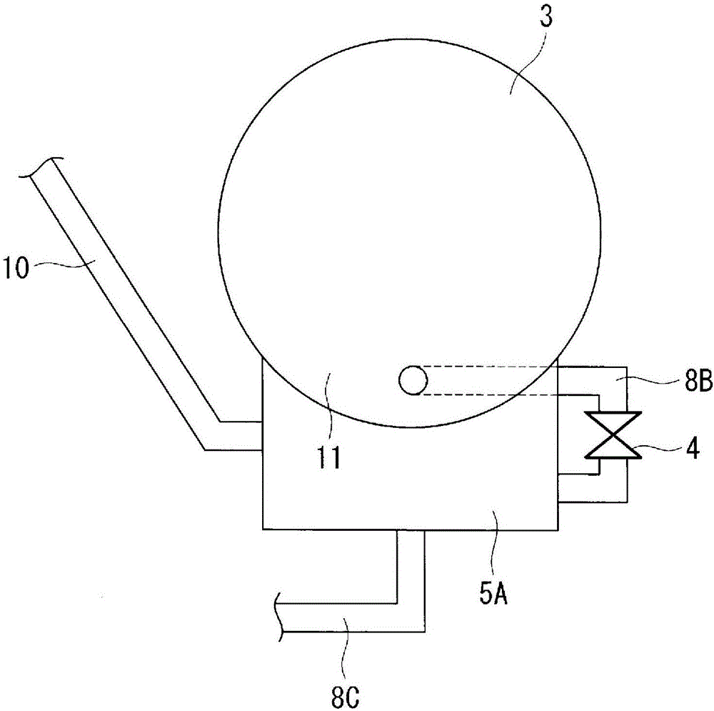
[0052] Next, use image 3 A second embodiment of the present invention will be described.

[0053] In this embodiment, the structure of the intercooler 5A integrated with the condenser 3 and the subcooler 11 is different from that of the above-mentioned first embodiment. Other points are the same as those of the first embodiment, and thus description thereof will be omitted.

[0054] In the present embodiment, the intercooler 5A is integrally formed with a part of the container wall as a common wall so as to cover substantially the entire bottom area of ​​the circular cavity-shaped container constituting the condenser 3 and the subcooler 11 .

[0055] In this manner, the intercooler 5A has an integral structure with a part of the container wall as a common wall so as to cover substantially the entire area of ​​the bottom of the condenser 3 and the subcooler 11 . Thus, the bottom of the condenser and the subcooler 11 where the condensed and liquefied refrigerant is deposited ...


PUM


Abstract

A turbo refrigeration machine (1) in which a closed-cycle refrigeration cycle (9) is formed by connecting a compressor (2), a condenser (3), an intercooler (5) and decompression means (4, 6) forming a multi-stage compression cycle, and an evaporator (7), with the refrigeration cycle (9) being charged with a low-pressure refrigerant. The condenser (3) and the intercooler (5) are integrated with each other by having a portion of their container walls form a shared wall, with the base surface of the intercooler (5) being positioned below the base surface of the condenser (3) and above the base surface of the evaporator (7).

Description

technical field [0001] The present invention relates to a turbo refrigerator filled with a low-pressure refrigerant such as HCFO refrigerant during a refrigeration cycle. Background technique [0002] Conventionally, in turbo refrigerators, HFC refrigerants such as R134a refrigerants have been used as refrigerants. It is known that the HFC refrigerant is a high-pressure refrigerant and has a high global warming factor (GWP). Against this backdrop, attention has recently been paid to R1233zd(E) refrigerant, one of HCFO (hydrochlorofluoroolefin) refrigerants that can reduce environmental burdens, and studies have begun to apply it to turbo refrigerators. The R1233zd(E) refrigerant is known to be a low-pressure refrigerant with a low density. [0003] In addition, in a turbo refrigerator using a high-pressure refrigerant, it is necessary to use a pressure vessel as a container for components such as a condenser, an evaporator, an intercooler, and a subcooler, and ensure stren...

Claims


Application Information

Patent Timeline
Patent Type & Authority Applications(China)
IPC IPC(8): F25B39/04F25B1/00F25B1/053F25B41/06F25B43/00
CPCF25B1/053F25B39/04F25B25/005F25B2339/047F25B2400/13F25B2400/23F25B2500/18F25B1/10F25B41/39F25B41/385F25B39/00F25B43/006
Inventor 三吉直也上田宪治长谷川泰士
Owner MITSUBISHI HEAVY IND THERMAL SYST
Why Eureka
Try Eureka