Method and device for microscopic examination of a sample

A technology for microscopes and samples, applied in microscopes, measuring devices, instruments, etc., can solve the problems of inability to flexibly and accurately set the precise position of sample irradiation, laborious layout and preparation, and impossible implementation of microscope inspection.

Active Publication Date: 2017-04-19
LEICA MICROSYSTEMS CMS GMBH
View PDF4 Cites 4 Cited by
  • Summary
  • Abstract
  • Description
  • Claims
  • Application Information

AI Technical Summary

Problems solved by technology

However, this setup has the disadvantage that the coupling of the irradiated light to the coverslip is not very efficient, so only a reduced amount of light is available for evanescently irradiating the sample
[0005] Furthermore, when it comes to the evanescent irradiation of the sample, the methods and devices known from the prior art generally have the disadvantage of not being able to flexibly and sufficiently accurately set the exact position of the sample irradiation
[0006] Furthermore, the methods and devices known from the prior art have the disadvantage that, prior to microscopic examination by evanescent radiation, samples have to be arranged and prepared laboriously in special sample chambers or between coverslips and then The sample chamber or the coverslip structure that mechanically holds the sample can be placed on the stage of the microscope
Often, just the edge regions of the sample at the boundary surfaces where total reflection should occur are damaged by continuous pressure stresses such that subsequent microscopic examination is minimally negatively affected or even completely impossible

Method used


Image

  • Method and device for microscopic examination of a sample
  • Method and device for microscopic examination of a sample
  • Method and device for microscopic examination of a sample

Examples


Embodiment Construction

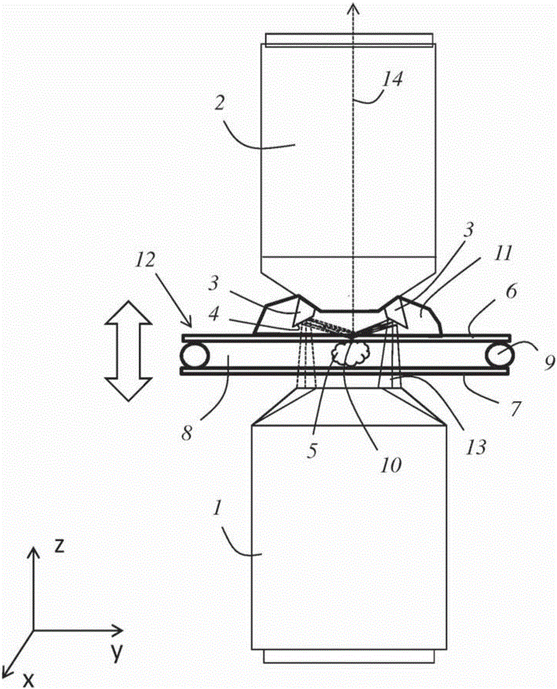
[0070] figure 1 A detailed view of a first embodiment of the device is shown, on the basis of which view a conceivable embodiment of the method according to the invention will be explained below.

[0071] The device has an irradiation objective 1 and a detection objective 2 configured as an oil objective. The optical axes of the irradiation objective 1 and the detection objective 2 are coaxial with each other, and they face in opposite directions. The deflection member 3 is attached to the detection objective 2 and has a frusto-conical mirror surface 4 .

[0072] The sample 5 to be examined is arranged in an aqueous nutrient medium between a first cover glass 6 and a second cover glass 7 . The coverslips 6 , 7 are sealed relative to each other by a surrounding gasket 9 so that the aqueous nutrient medium 8 cannot escape.

[0073] Between the cover glass 6 facing the detection objective 2 and the detection objective 2 there is immersion oil 11 in which the deflection member ...


PUM


Abstract

The invention relates to a method for microscopically examining a sample (5). The method includes the steps: bringing the sample (5) into contact with an optically transparent medium (12) which has a higher refraction index than the sample (5), generating an illumination light beam (13), and guiding the illumination light beam (13) through an illumination lens (1) which focuses the illumination light beam. Subsequently, the deflecting of the illumination light beam (13) is carried out in the direction of the sample (5) to be examined using a deflection means arranged on a detection lens (2), in such a way that the illumination light beam hits an interface (10) between the optically transparent medium (12) and the sample (5) and is there completely reflected for evanescent illumination of the sample (5). Finally, detection is carried out of the fluorescent light emitted by the sample (5) and passing through the detection lens (2).

Description

technical field [0001] The invention relates to a method for microscopic examination of a sample, and also to a device for performing such a method. Background technique [0002] In the context of microscopic fluoroscopic examination of samples, the sample is usually irradiated directly with a radiation beam, so that the sample is optically excited in the irradiated region and the fluorescence emitted by the sample is subsequently detected. In scanning microscopes, the focus of the radiation beam is directed in a serpentine pattern across or through the sample, and in this way one point at a time, the sample is scanned using controllable beam deflecting components, which may include For example one or more tilting mirrors. [0003] As an alternative to direct sample irradiation, it is also possible to evanescently irradiate the sample. Here, the excitation light is totally reflected to the sample on the boundary surface, whereby the sample is excited by the evanescent elec...

Claims


Application Information

Patent Timeline
Patent Type & Authority Applications(China)
IPC IPC(8): G01N21/64G02B21/06G02B21/16G02B27/56
CPCG01N21/6458G01N21/648G02B21/06G02B21/16G02B27/56G02B21/002
Inventor W·奈彼尔
Owner LEICA MICROSYSTEMS CMS GMBH
Why Eureka
Try Eureka