Heat-dissipating structure

A heat sink and heat sink technology, applied in the direction of heat transfer modification, arrangement of circuit elements without support structure, heat exchange equipment, etc., can solve the problems of increasing resistance, increasing power loss, etc., and achieve lower resistance and high heat dissipation sexual effect

Active Publication Date: 2017-04-19
SHINDENGEN ELECTRIC MFG CO LTD
View PDF8 Cites 4 Cited by
  • Summary
  • Abstract
  • Description
  • Claims
  • Application Information

AI Technical Summary

Problems solved by technology

However, under this structure, due to the increase in the number of wiring and the complexity of the wiring arrangement, the resistance is increased, thereby increasing the power loss (Loss)

Method used


Image

  • Heat-dissipating structure
  • Heat-dissipating structure
  • Heat-dissipating structure

Examples


Embodiment Construction

[0038] Hereinafter, embodiments of the present invention will be described in detail with reference to the accompanying drawings.

[0039] In the following description, in order to facilitate the identification of each constituent element, there may be situations in which different scaling factors are marked in the drawings according to different constituent elements.

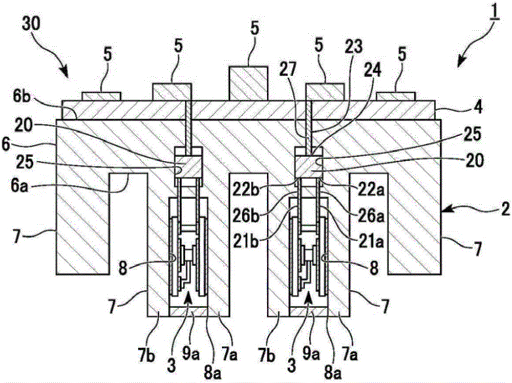
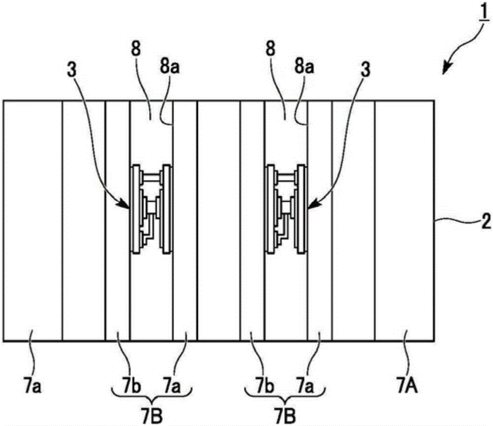
[0040] refer to figure 1 as well as figure 2 The heat radiation structure 1 which is one embodiment of this invention is demonstrated.

[0041] Heat dissipation structure 1 such as figure 1 as well as figure 2 As shown, in a semiconductor device including a heat sink 2, a plurality of semiconductor modules (first heat generating components) 3, a circuit substrate 4, and a plurality of electronic components (second heat generating components) 5, the semiconductor A structure in which the heat emitted by the module 3 and the electronic component 5 is dissipated.

[0042] Specifically, in the heat dissipati...


PUM


Abstract

A heat sink according to one embodiment of the present invention includes: a base section having first and second surfaces opposite one another; one or more heat-dissipating fins extending perpendicularly from the first surface, and each having an insertion groove extending toward the base section from the tip end thereof, and first and second fin sections divided by the insertion groove; and a connector configured so as to electrically connect a first heat-generating component to be inserted into the insertion groove from the first surface side and a second heat-generating component positioned on the second surface side with one another, and so as to be inside the base section and in the insertion groove when seen from a planar view.

Description

technical field [0001] The invention relates to a heat dissipation structure. [0002] This application claims priority based on International Application No. PCT / JP2014 / 078744 filed in Japan on October 29, 2014, and uses the content thereof here. Background technique [0003] For example, the use of a heat sink is widely known as a heat dissipation structure for heat-generating components such as electronic components (see Patent Document 1). In the heat dissipation structure of Patent Document 1, a heat sink including a base portion and a plurality of fins (Fin) provided on a first surface of the base portion is used. On the second surface opposite to the first surface of the base portion, all heat generating components to be cooled are disposed. After the heat of the heating component is conducted to the heat sink through the base part, the heat is then dissipated to the outside by the heat sink. [0004] Prior art literature [0005] patent documents [0006] Patent...

Claims


Application Information

Patent Timeline
Patent Type & Authority Applications(China)
IPC IPC(8): H01L23/36H01L25/07H01L25/18H05K7/20
CPCH01L23/36H01L25/07H01L25/18H01L2924/0002H01L23/3672H01L25/072H01R12/7082H05K7/209H01L2924/00F28F13/08F28F2013/005H05K7/005H05K7/1053H05K7/20409
Inventor 池田康亮森永雄司松嵜理
Owner SHINDENGEN ELECTRIC MFG CO LTD
Why Eureka
Try Eureka