
Semi-automatic garlic planter

A planting machine and semi-automatic technology, applied in the field of agricultural machinery, can solve the problems of inability to realize upright planting with cusps upward, irregular shape of garlic seeds, failure to meet the requirements of garlic planting, etc., and achieve simple structure, good adaptability and practicability strong effect

Active Publication Date: 2017-04-26
SHANDONG UNIV OF TECH
View PDF7 Cites 4 Cited by
  • Summary
  • Abstract
  • Description
  • Claims
  • Application Information

AI Technical Summary

Problems solved by technology

[0002] Due to the irregular shape of garlic seeds and the need for a single cusp to be planted upright, it is difficult to realize mechanized planting. The current garlic planting mainly relies on manual planting, which is labor-intensive and low in planting efficiency. Therefore, garlic planting machinery that replaces manual planting is urgently needed
At present, there are two main types of garlic planters, one is traction type, and the other is self-propelled. The traction type garlic planter has a simple structure and small dimensions, but most of them cannot achieve vertical planting with the cusps upward. Orientation of garlic seeds or single-grain orientation is completely done manually by planting with the cusp upright; the self-propelled garlic planter has a complex structure and basically has the function of planting with the cusp upright, but manual assistance is required to orientate or ensure single-grain garlic planting. Seed sorting, low operating speed, low vertical planting rate, can not meet the requirements of garlic planting, and the adaptability of the orientation device to garlic varieties is poor

Method used


Image

  • Semi-automatic garlic planter
  • Semi-automatic garlic planter
  • Semi-automatic garlic planter

Examples


Embodiment Construction

[0025] Embodiments of the present invention are further described below in conjunction with accompanying drawings:

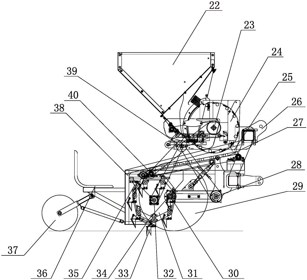
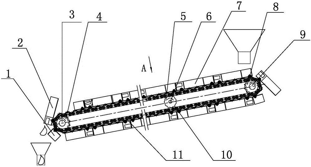
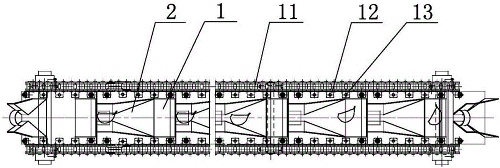
[0026] Such as figure 1 As shown, the semi-automatic garlic planter of the present invention includes a fixed bracket 38, the top of the fixed bracket 38 fixes the seed box 22 and the seed meter 24, the outlet of the seed box 22 corresponds to the entrance of the seed meter 24, and the seed meter 24 The seed discharge port 25 of 24 corresponds to the combined hopper 7 arranged at the front end of the orientation device 27 below the seed meter 24, and the end of the corresponding orientation device 27 is provided with a hopper II 35 below it, and a vertical seeding turntable 31 is fixed below the hopper II 35 The outlet of the receiving hopper II 35 corresponds to the duckbill 33 arranged on the vertical seed turntable 31. There are multiple duckbills 33 and are evenly distributed on the vertical seed turntable 31 along the circumference. The matching duckbill o...


PUM


Abstract

The invention relates to a semi-automatic garlic planter, and belongs to the technical field of agricultural machinery. The planter includes a fixed bracket; a seed case and a seed metering device are fixed to the upper part of the fixed bracket; the outlet of the seed case corresponds to the inlet of the seed metering device; the seed outlet of the seed metering device corresponds to a combination hopper disposed at the front end of an orienting device located below the seed metering device; a receiving hopper II is disposed below the front end of the orienting device correspondingly; a vertical seeding rotating disc is fixed below the receiving hopper II; the outlet of the receiving hopper II corresponds to duckbill components set on the vertical planting turntable; a duckbill opening cam that cooperates with the opening of each duckbill component is set under the vertical seeding rotating disc; a land wheel is arranged at the lower part of the fixed bracket; a seat and a pressing wheel are arranged at the rear of the fixed bracket; and a hanger is provided at the front end of the fixed bracket. The semi-automatic garlic planter has the advantages of simple structure and reasonable design, can realize the vertical planting of garlic with the tooth tip upward, has a high vertical planting rate, and can realize oriented as well as fixed-distance planting, and reduce the labor intensity of the staff.

Description

technical field [0001] The invention relates to a semi-automatic garlic planter, which belongs to the technical field of agricultural machinery. Background technique [0002] Due to the irregular shape of garlic seeds and the need for a single cusp to be planted upright, it is difficult to realize mechanized planting. The current garlic planting mainly relies on manual planting, which is labor-intensive and low in planting efficiency. Therefore, garlic planting machinery that replaces manual planting is urgently needed. At present, there are two main types of garlic planters, one is traction type, and the other is self-propelled. The traction type garlic planter has a simple structure and small dimensions, but most of them cannot achieve vertical planting with the cusps upward. Orientation of garlic seeds or single-grain orientation is completely done manually by planting with the cusp upright; the self-propelled garlic planter has a complex structure and basically has the f...

Claims


Application Information

Patent Timeline
Patent Type & Authority Applications(China)
IPC IPC(8): A01C7/04
CPCA01C7/04
Inventor 宋井玲崔志超徐陶李宁蔡善儒马伟童孙倩金诚谦
Owner SHANDONG UNIV OF TECH
Learn More