A quick-loading tool

A quick-installation and cutting tool technology, which is applied in the direction of drilling tool accessories, tool joints, manufacturing tools, etc., can solve the problems of poor installation convenience, low clamping accuracy, and poor rigidity of the tool body and tool handle, and achieve disassembly and assembly efficiency. High, high processing precision, strong rigidity effect

Active Publication Date: 2018-05-29
ZHEJIANG XINXING TOOLS CO LTD
View PDF9 Cites 0 Cited by
  • Summary
  • Abstract
  • Description
  • Claims
  • Application Information

AI Technical Summary

Problems solved by technology

Because the technology of this kind of split tool has not yet matured, there are technical defects such as poor rigidity, low clamping accuracy, and poor installation convenience of the tool body and tool handle.

Method used


Image

  • A quick-loading tool
  • A quick-loading tool
  • A quick-loading tool

Examples


Embodiment 1

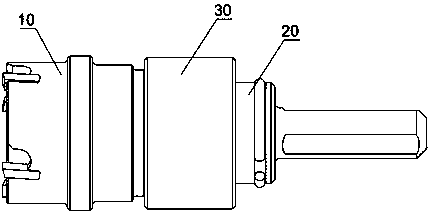
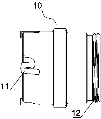
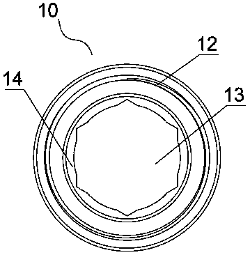
[0030] Such as figure 1 As shown, a quick-install tool in this embodiment includes a tool body 10 , a tool handle 20 and a fixing sleeve 30 . Such as figure 2 , image 3 As shown, one end of the cutter body 10 is provided with a cutting edge 11, and the other end is provided with an external thread 12, and one end of the cutter body 10 provided with the external thread 12 is provided with a connecting hole extending axially from the end face, and the connecting hole includes a column Shaped hole segment 14 and polygonal hole segment 13, and the inner diameter of the cylindrical hole segment 14 is not less than the circumscribed circle diameter of the polygonal hole segment 13, wherein the cylindrical hole segment 14 is located at the end of the cutter body near the external thread 12. It should be noted that the cross-section of the above-mentioned polygonal hole segment can be a polygonal hole that is equally or unequally divided, and the number of specific edges is not li...

Embodiment 2

[0037] Such as figure 1 As shown, a quick-install tool in this embodiment includes a tool body 10 , a tool handle 20 and a fixing sleeve 30 . Such as figure 2 , image 3 As shown, one end of the cutter body 10 is provided with a cutting edge 11, and the other end is provided with an external thread 12, and one end of the cutter body 10 provided with the external thread 12 is provided with a connecting hole extending axially from the end face. The cross-sectional outer contour includes at least an arc segment and a straight line segment. Correspondingly, as Figure 7As shown, one end of the handle 20 is provided with a connecting section 25 matching the connecting hole and a limiting boss 23 , the outer diameter of the limiting boss 23 is larger than the outer diameter of the circumscribed circle of the connecting section 25 .

[0038] Such as Figure 8 As shown, the cross-sectional outer profile of the connecting section 25 includes at least an arc segment 251 and a stra...


PUM


Abstract

The invention relates to the technical field of cutting tools, discloses a cutter whose cutter body and shank are separated, and particularly provides a rapidly installed cutter. The cutter adopting the structure is characterized in that corresponding structures for realizing radial positioning, limiting in peripheral direction and torque transmission are arranged between the cutter body and the shank, thereby having the technical advantages of high machining precision, high installation precision, stable rotation and cutting, large transmission torque and higher rigidity; meanwhile, the cutter body and the shank are connected through threads of a fixing sleeve and the cutter body, and the technical advantages of convenient uninstallation and installation and high uninstallation and installation efficiency are realized; an elastic piece is arranged between a limiting boss and an annular step and is in a compressed state when the cutter body and a cutter head are connected, a damping action is realized by elastic force, loose threaded connection caused by vibration in a drilling process is prevented, and the drilling force is enabled to be more steady in the drilling machining process.

Description

technical field [0001] The invention relates to the technical field of cutting tools, in particular to a tool in which a tool body and a handle are separated, especially a quick-loading tool. Background technique [0002] At present, common cutting tools have an integrated structure of the tool body and the tool handle. This type of cutting tool has the advantages of strong rigidity, high machining accuracy and high installation accuracy. However, this type of cutting tool also has corresponding technical defects. The tool body will inevitably wear during the cutting process, and the tool needs to be replaced after cutting for a certain period of time. The one-piece structure tool needs to replace both the tool body and the tool handle. For the enterprise, replacing the tool handle without wear will inevitably increase the cost. At the same time, during the cutting process, if it is necessary to replace a tool with a different specification, the entire tool needs to be clam...

Claims


Application Information

Patent Timeline
Patent Type & Authority Patents(China)
IPC IPC(8): B23B51/12
CPCB23B51/12B23B2251/02
Inventor 朱冬伟杨雪丁金安生
Owner ZHEJIANG XINXING TOOLS CO LTD
Why Eureka
Try Eureka